Refine search
Actions for selected content:
148 results
Mechanical loads from simulated lightning strike on protected carbon fibre-reinforced polymers revisited: implementation and experimental validation
-
- Journal:
- The Aeronautical Journal , First View
- Published online by Cambridge University Press:
- 11 August 2025, pp. 1-33
-
- Article
-
- You have access
- Open access
- HTML
- Export citation
7 - Solving differential equations
- from Part I - Areas of application
-
- Book:
- Quantum Algorithms
- Published online:
- 03 May 2025
- Print publication:
- 24 April 2025, pp 111-129
-
- Chapter
-
- You have access
- Open access
- Export citation
13 - Hull Girder Strength Assessment Using the Finite Element Method
-
- Book:
- Global Strength of Ships
- Published online:
- 20 March 2025
- Print publication:
- 03 April 2025, pp 628-671
-
- Chapter
- Export citation

Global Strength of Ships
- Analysis and Design using Mathematical Methods
-
- Published online:
- 20 March 2025
- Print publication:
- 03 April 2025
Finite element approximations for stochastic control problems with unbounded state space
- Part of
-
- Journal:
- Journal of Applied Probability / Volume 62 / Issue 1 / March 2025
- Published online by Cambridge University Press:
- 03 October 2024, pp. 367-394
- Print publication:
- March 2025
-
- Article
-
- You have access
- Open access
- HTML
- Export citation
FEM-based eigenstructure recovery of a space truss with active members
-
- Journal:
- The Aeronautical Journal / Volume 128 / Issue 1327 / September 2024
- Published online by Cambridge University Press:
- 08 April 2024, pp. 2023-2037
-
- Article
- Export citation
12 - Scale C
- from Part III - Applications I
-
- Book:
- Field Theory of Multiscale Plasticity
- Published online:
- 14 December 2023
- Print publication:
- 04 January 2024, pp 604-678
-
- Chapter
- Export citation
11 - Scale B
- from Part III - Applications I
-
- Book:
- Field Theory of Multiscale Plasticity
- Published online:
- 14 December 2023
- Print publication:
- 04 January 2024, pp 545-603
-
- Chapter
- Export citation
Neural network ensembles and uncertainty estimation for predictions of inelastic mechanical deformation using a finite element method-neural network approach
- Part of
-
- Journal:
- Data-Centric Engineering / Volume 4 / 2023
- Published online by Cambridge University Press:
- 23 October 2023, e23
-
- Article
-
- You have access
- Open access
- HTML
- Export citation
1 - Introduction
-
- Book:
- Computational Grains
- Published online:
- 05 October 2023
- Print publication:
- 19 October 2023, pp 1-16
-
- Chapter
-
- You have access
- HTML
- Export citation
2 - Computational Homogenization in the Micromechanics of Heterogeneous Materials
-
- Book:
- Computational Grains
- Published online:
- 05 October 2023
- Print publication:
- 19 October 2023, pp 17-26
-
- Chapter
- Export citation
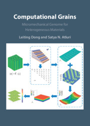
Computational Grains
- Micromechanical Genome for Heterogeneous Materials
-
- Published online:
- 05 October 2023
- Print publication:
- 19 October 2023
4 - Fundamentals of Crystal Plasticity Finite Element Method
-
- Book:
- Computational Design of Engineering Materials
- Published online:
- 29 June 2023
- Print publication:
- 29 June 2023, pp 95-112
-
- Chapter
- Export citation
7 - Case Studies on Steel Design
-
- Book:
- Computational Design of Engineering Materials
- Published online:
- 29 June 2023
- Print publication:
- 29 June 2023, pp 264-294
-
- Chapter
- Export citation
ELECTRICAL IMPEDANCE TOMOGRAPHY USING NONCONFORMING MESH AND POSTERIOR APPROXIMATED REGRESSION
- Part of
-
- Journal:
- Bulletin of the Australian Mathematical Society / Volume 105 / Issue 3 / June 2022
- Published online by Cambridge University Press:
- 03 March 2022, pp. 520-522
- Print publication:
- June 2022
-
- Article
-
- You have access
- HTML
- Export citation
Potential of surrogate modelling in compressor casing design focussing on rapid tip clearance assessments
-
- Journal:
- The Aeronautical Journal / Volume 125 / Issue 1291 / September 2021
- Published online by Cambridge University Press:
- 13 September 2021, pp. 1587-1610
-
- Article
- Export citation
GEOMETRICALLY FLEXIBLE AND EFFICIENT NUMERICAL SOLUTION TECHNIQUE FOR BRAGG EDGE NEUTRON TRANSMISSION STRAIN TOMOGRAPHY
- Part of
-
- Journal:
- Bulletin of the Australian Mathematical Society / Volume 104 / Issue 3 / December 2021
- Published online by Cambridge University Press:
- 12 August 2021, pp. 522-524
- Print publication:
- December 2021
-
- Article
-
- You have access
- HTML
- Export citation
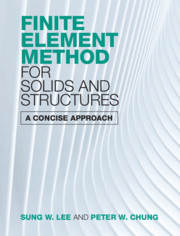
Finite Element Method for Solids and Structures
- A Concise Approach
-
- Published online:
- 08 July 2021
- Print publication:
- 17 June 2021
-
- Textbook
- Export citation
1 - Introduction to the Finite Element Method
-
- Book:
- Finite Element Method for Solids and Structures
- Published online:
- 08 July 2021
- Print publication:
- 17 June 2021, pp 1-41
-
- Chapter
- Export citation
