I. INTRODUCTION
The fundamental problem for the real-time delivery of compressed video is to ensure that every compressed picture can be decoded (or presented) in the receiver at its pre-determined decoding (or presentation) time. For a carrier-grade IP video, it often means the compressed video delivered over the IP network with a carrier-grade quality (in terms of image distortion and spatial resolution) as the traditional broadcasting video. Frequently the pre-determined decoding (or presentation) time is captured (or derived) as the decoding (or presentation) timestamp for each picture. Such timestamp is a function of the end-to-end delay from the encoder output to the decoder input. In general, the end-to-end delay relates to coding buffer delay, burstiness of coded video, switching/routing delay and jitter, transmission propagation delay, transmission rate, etc. [Reference Chen1–Reference Cruz5].
There were several in-depth analyses in the past on the relationships of video buffer delay, transmission rate, and encoding and decoding times. For example, in [Reference Chen1,Reference Sun, Chen and Chiang2], the conditions for preventing decoder buffer underflow and overflow for the constant-delay channel have been analyzed by using the encoding timing, decoding timestamp, transmission rate, and compressed picture sizes. However, these results did not address any IP-network-related delay and jitter, and their associated transmission rate for quality of service (QoS). In [Reference Reibman and Haskell6], an analysis on the picture sizes and buffer constraints for managing the channel rate control for ATM networks was presented. However, the result does not associate the buffer dynamics with the encoding and decoding timestamps, nor does it address QoS.
Network QoS provides the desired levels of service guarantee with respect to latency (delay), jitter (variability), and throughput (capacity). For a guaranteed QoS service in IP network, the Traffic Specification (TSpec) describes the traffic source characteristics (e.g., average and peak rates, burstiness, and packet size information), while the Service Request Specification (RSpec) provides the minimum reserved capability (e.g. transmission rate and delay bound) [7–Reference Forouzan10]. The traffic characteristic is usually modeled by the token bucket, and TSpecs typically just specify the token rate and the bucket depth [7–Reference Forouzan10]. To achieve a carrier-grade real-time video delivery, it is desirable to extract the video source characteristics (e.g., bit rates, compressed picture sizes, and frame rate) for determining TSpec and RSpec parameters, including token rate, bucket depth, and delay information.
In this paper, we develop a mathematical theory of video buffering for providing IP video traffic regulations with respect to picture size, buffer size and fullness levels, and coding time. To achieve the real-time delivery of compressed video, we also derive some key parameters related to end-to-end network QoS such as video rate and burstiness, as well as network delay and jitter. In particular, we address the following video delivery issues:
(1) Given a video source and the network delay and jitter, what are the constraints on the network rate and video buffers (Section 2)?
(2) Given a video source, how should the network QoS be provisioned in terms of data burst (Section 4) and rate (Section 5)?
In addition, this paper demonstrates the applicability of this theory to some real-world video transmission examples.
II. VIDEO BUFFER DYNAMICS
In video compression standards, such as MPEG-2, H.264/ MPEG-4 advanced video coding (AVC), and H.265/MPEG-H high-efficiency video coding (HEVC), a hypothetical reference decoder or a video buffer verifier [Reference Chen1,Reference Sun, Chen and Chiang2] is specified for modeling the transmission of compressed video data from the video encoder to the video decoder. A video buffer model usually imposes constraints on the variations in bit rate over time in a compressed bit stream regarding timing and buffering. Such a model has been particularly important in the past for carrier-grade video transmission, e.g., digital video broadcasting via cable and satellite.
Consider a digital video with the picture time (or the frame time) ![]() $t \grave{o} T=\{T_{0},T_{1},\ldots,T_{N-1}\}$ with
$t \grave{o} T=\{T_{0},T_{1},\ldots,T_{N-1}\}$ with ![]() $T_{i+1} = T_{i} + 1/f$, where f is the video frame rate (or the picture rate), e.g., 30 frames per second. For delivering carrier-grade compressed digital video, the video buffer manager in an encoder or a video server provides a mechanism to prevent decoder buffer underflow and/or overflow. In [Reference Chen1,Reference Sun, Chen and Chiang2], this has been extensively analyzed for digital video broadcasting. The high-level system model used in [Reference Chen1,Reference Sun, Chen and Chiang2] can be shown in Fig. 1.
$T_{i+1} = T_{i} + 1/f$, where f is the video frame rate (or the picture rate), e.g., 30 frames per second. For delivering carrier-grade compressed digital video, the video buffer manager in an encoder or a video server provides a mechanism to prevent decoder buffer underflow and/or overflow. In [Reference Chen1,Reference Sun, Chen and Chiang2], this has been extensively analyzed for digital video broadcasting. The high-level system model used in [Reference Chen1,Reference Sun, Chen and Chiang2] can be shown in Fig. 1.

Fig. 1. Video encoder and decoder buffer model for digital video broadcasting.
In this buffer model, a video encoder generates a sequence of compressed pictures and then puts these pictures into the encoder buffer for transmission. The video buffers are characterized by the following set of parametersFootnote 1:
• $B_{E}^{MAX}:$ The encoder buffer size.
• $P_{E}^{j}:$ The size of the jth compressed picture.
• $\bar{B}^{j}_{E}:$ The encoder buffer level immediately before the jth compressed picture is inserted into the encoder buffer, and $P_{E}^{j} +\bar{B}_{E}^{j} \leq B_{E}^{MAX}$.
• $R_{e}^{MAX}:$ The maximum encoder buffer output data rate.
• $\bar{R}_{e}(t):$ The encoder buffer output data rate function and $\bar{R}_{e}(t)\leq R_{e}^{MAX}$.
• R d (t): The decoder buffer input data rate function and $R_{d} (t)=\bar{R}_{e}(t)$.
• $\bar{B}_{D}^{MAX}:$ The decoder buffer size.
• $\bar{B}^{j}_{D}:$ The decoder buffer level immediately before the jth compressed picture is inserted into the encoder buffer, and $\bar{B}^{j}_{D} \leq \bar{B}_{D}^{MAX}$.
• t e, j: The encoding time of the jth picture, which is the time immediately before the jth compressed picture is inserted into the encoder buffer and $t_{e,j} \grave{o} T$.
• t d, j: The decoding time of the jth picture, which is the time immediately before the jth compressed picture is removed from the decoder buffer and $t_{d,j} \grave{o} T$.
Note that we do not make any assumption on resolutions of the video.
Assume that the video delivery system preserves the original video frame rate, i.e., neither inserting nor dropping pictures. Then, the encoding and decoding times satisfy the following equations:
And, if there is no network delay [Reference Chen1,Reference Sun, Chen and Chiang2],
where c≥1 is a constant. Without loss of generality, assume c≥1 is an integer. Note that if c is not an integer, we can use c. Equation (3) implies that after a picture is (instantaneously) placed into the encoder buffer, it will take c/f seconds before it is instantaneously removed from the decoder buffer. Note that there are c compressed pictures residing in the encoder and decoder buffers at the time t e, j, i.e., ![]() $\bar{B}^{j}_{E} + \bar{B}^{j}_{D}$ are data of c consecutive compressed pictures. In this case, we can define:
$\bar{B}^{j}_{E} + \bar{B}^{j}_{D}$ are data of c consecutive compressed pictures. In this case, we can define:
For this video buffer model, a set of necessary and sufficient conditions for preventing decoder buffer underflow and overflow have been proven in [Reference Chen1,Reference Sun, Chen and Chiang2].
In this paper, we will generalize the buffer dynamics described in [Reference Chen1,Reference Sun, Chen and Chiang2] to generic IP video distribution cases. First, we will determine some general conditions for preventing decoder buffer underflow and/or overflow.
Consider an IP video delivery system where a compressed video stream is transmitted sequentially, picture-by-picture, from an encoder or video server to multiple decoders in the network as shown in Fig. 2. For a high-level mathematical model of such system shown in Fig. 3, the video buffers can be characterized with the following additional set of parametersFootnote 2:
• $B_{E}^{j}:$ The encoder buffer level immediately before the jth compressed picture is inserted into the encoder buffer. Note that this can be the same as $\bar{B}^{j}_{E}$ in the buffer model for digital video broadcasting (Fig. 1), i.e., $B_{E}^{j} =\bar{B}^{j}_{E}$.
• $B_{D,k}^{MAX}:$ The decoder buffer size of the kth video path.
• $B_{D,k}^{j}:$ The decoder buffer level of the kth video path immediately before the jth compressed picture is inserted into the encoder buffer, and $B_{D,k}^{j} \le B_{D,k}^{MAX}$.
• $B_{N,k}^{j}:$ The total network buffer level of the kth video path immediately before the jth compressed picture is inserted into the encoder buffer.
• t d, j, k: The decoding time of the jth picture for the kth video path, which is the time immediately before the jth compressed picture is removed from the decoder buffer and $t_{d,j,k} \grave{o} T$.
• R e (t): The encoder buffer output data rate function.
• R d, k (t): The decoder buffer input data rate function of the kth video path for the video transmission.

Fig. 2. An IP video delivery system.

Fig. 3. End-to-end kth video path.
Assume that the end-to-end IP video data transmission has no loss and is in first-in-first-out (FIFO) order in both the encoder and decoder buffers. Also, for simplicity, assume that the network buffers along each video path are represented by an aggregate network buffer B N, k and that compressed pictures are transmitted along any video path as individual impulsesFootnote 3; these two assumptions will be relaxed in Section 6. With these assumptions, the end-to-end kth video path from the encoder to the decoder is shown in Fig. 3. Now we have:
i.e.,
where j is the compressed-picture index, ![]() $\sigma_{k} \ge 0$ is a constant, and σk/f is the network buffer delay for the kth video path. Without loss of generality, assume σk is an integer for the kth video path. Note that if σk is not an integer, we can use σk.
$\sigma_{k} \ge 0$ is a constant, and σk/f is the network buffer delay for the kth video path. Without loss of generality, assume σk is an integer for the kth video path. Note that if σk is not an integer, we can use σk.
To ensure correct picture timing for video coding and transmission, the following conditions must be satisfied:
Theorem 1
for the video transmission system described in Fig. 3, the decoder buffer for the kth video path will not underflow, if and only if
 $$P_E^j + B_E^j + B_{N,k}^j \le \int_{t_{e,j}}^{t_{d,j,k}} R_{d,k} (t)dt, \forall j.$$
 Proof: In order to avoid decoder buffer underflow, it requires that for all j, all the compressed data in the encoder and the network buffers up to and including picture j, i.e., ![]() $P_{E}^{j} +B_{E}^{j} +B_{N,k}^{j}$ be completely transmitted to the decoder buffer before the required decoding time t d, j, k. Therefore, inequality equation (7) follows.
$P_{E}^{j} +B_{E}^{j} +B_{N,k}^{j}$ be completely transmitted to the decoder buffer before the required decoding time t d, j, k. Therefore, inequality equation (7) follows.
However, if there exists j such that  $P_{E}^{j} +B_{E}^{j} +B_{N,k}^{j} \gt \int_{t_{e,j}}^{t_{d,j,k}} R_{d,k} (t)dt$, then the data of
 ![]() $P_{E}^{j} $ will not have completely arrived at the decoder buffer since the data transmission is in FIFO order; that is, the decoder buffer will underflow. This completes the proof.□
$P_{E}^{j} $ will not have completely arrived at the decoder buffer since the data transmission is in FIFO order; that is, the decoder buffer will underflow. This completes the proof.□
Theorem 2
for the video transmission system described in Fig. 3, the decoder buffer for the kth video path will not overflow, if and only if
 $$\int_{t_{e,j}}^{t_{d,j,k}} R_{d,k} (t)dt-(B_E^j +B_{N,k}^j)\le B_{D,k}^{MAX},\forall j.$$
 Proof: In order to avoid decoder buffer overflow, it requires that for all j, the decoder buffer fullness at time t d, j, k (immediately before the jth compressed picture is removed from the decoder buffer) must be less than or equal to ![]() $B_{D,k}^{MAX}$. From the time t e, j to t d, j, k, the number of bits arriving at the decoder buffer will be
$B_{D,k}^{MAX}$. From the time t e, j to t d, j, k, the number of bits arriving at the decoder buffer will be  $\int_{t_{e,j}}^{t_{d,j,k}} R_{d,k} (t) dt $ and the number of bits removed from the decoder buffer will be all the compressed video data before the jth picture in the encoder buffer, the network buffer, and the decoder buffer at time t e, j, i.e.,
 ![]() $B_{E}^{j} +B_{N,k}^{j} +B_{D,k}^{j} $. Thus, the decoder buffer fullness at time t d, j, k satisfies:
$B_{E}^{j} +B_{N,k}^{j} +B_{D,k}^{j} $. Thus, the decoder buffer fullness at time t d, j, k satisfies:
 $$\left(\int_{t_{e,j}}^{t_{d,j,k}} R_{d,k} (t)dt + B_{D,k}^j \right) - (B_E^j +B_{N,k}^j +B_{D,k}^j)\le B_{D,k}^{MAX}.$$
Therefore, the inequality equation (8) follows. However, if there exists j, such that  $\int_{t_{e,j}}^{t_{d,j,k}} R_{d,k} (t)dt-(B_{E}^{j} +B_{N,k}^{j}) \gt B_{D,k}^{MAX}$, then some data in
 ![]() $P_{E}^{j}$ will be lost before it is removed from the decoder buffer for decoding since the data transmission is in FIFO order, i.e., the decoder buffer will overflow. This completes the proof.□
$P_{E}^{j}$ will be lost before it is removed from the decoder buffer for decoding since the data transmission is in FIFO order, i.e., the decoder buffer will overflow. This completes the proof.□
Note that there are c+σk compressed pictures residing in the encoder buffer, the network buffer, and the decoder buffer at the time t e, j, i.e., ![]() $B_{E}^{j} +B_{N,k}^{j} +B_{D,k}^{j} $ are data of c+σk consecutive compressed pictures. In this case, we can now define:
$B_{E}^{j} +B_{N,k}^{j} +B_{D,k}^{j} $ are data of c+σk consecutive compressed pictures. In this case, we can now define:
where ![]() $R_{e,d,k}^{MAX} = \mathop{\max}\nolimits_{j,t_{e,j} \le t\le t_{d,j,k}} (R_{e} (t),R_{d,k} (t))$. As can be seen from equation (10), the decoder buffer size is a network-delay-dependent parameter.
$R_{e,d,k}^{MAX} = \mathop{\max}\nolimits_{j,t_{e,j} \le t\le t_{d,j,k}} (R_{e} (t),R_{d,k} (t))$. As can be seen from equation (10), the decoder buffer size is a network-delay-dependent parameter.
For a constant-delay network, as shown in Fig. 4, where the delay between the output of the encoder buffer and the input of the decoder buffer is a constant, we can obtain the following simplified conditions on video buffer dynamics with the decoder buffer size being independent of the network-delay. Without loss of generality, assume that the constant delay Δk is an integer (if it is not, Δk can be used).
Corollary 1
if the network link for the kth video path has a fixed delay Δk/f between the output of the encoder buffer and the input of the decoder buffer at t ò T for all j, then
(1) The decoder buffer will not underflow, if and only if
(11) $$P_E^j +B_E^j \le \int_{t_{e,j} +{\Delta_k \over f}}^{t_{d,j,k}} R_{d,k} (t)dt, \forall j.$$
(2) The decoder buffer will not overflow, if and only if
(12) $$\int_{t_{e,j} + {\Delta_k \over f}}^{t_{d,j,k}} R_{d,k} (t)dt - B_E^j \le \bar{B}_D^{MAX}, \forall j,$$
where the decoder buffer size ![]() $\bar{B}_{D}^{MAX}$ is given in equation (4).
$\bar{B}_{D}^{MAX}$ is given in equation (4).

Fig. 4. Network link for the kth video path with a fixed delay Δk/f.
Corollary 1 (Appendix for proof) provides a set of conditions on the video bit rate, frame rate, encoding/decoding time, video buffers, and network delay for the system model given in Fig. 4. These conditions ensure correct video timing for end-to-end video transmission. This system is applicable to live digital video broadcasting services, e.g., today's cable and satellite live pay-TV broadcasting services. If Δk=0, then the conditions provided by inequalities equations (11) and (12) for preventing decoder buffer underflow and overflow are the same as those for the system model shown in Fig. 1.
Corollary 1 also gives the fact that, for a constant-delay network path k, the actual decoder buffer size is independent of the network-delay parameter Δk. However, if such a network path has a maximum jitter integer parameter ![]() $\delta_{k} \ge 0$, i.e., the network-delay will vary between Δk/f and
$\delta_{k} \ge 0$, i.e., the network-delay will vary between Δk/f and ![]() $\Delta_{k} +\delta_{k} /f$, we will have a system model as shown in Fig. 5. Without loss of generality, assume δk is an integer (again, if δk is not an integer, δk can be used). We can prove the following corollary (Appendix for proof).
$\Delta_{k} +\delta_{k} /f$, we will have a system model as shown in Fig. 5. Without loss of generality, assume δk is an integer (again, if δk is not an integer, δk can be used). We can prove the following corollary (Appendix for proof).
Corollary 2
if the network link for the kth video path between the output of the encoder buffer and the input of the decoder buffer has a fixed delay Δk/f with a jitter δk/f at t ò T for all j, then
(1) The decoder buffer will not underflow if
(13) $$P_E^j +B_E^j \le \int_{t_{e,j} +{\Delta_k +\delta_k \over f}}^{t_{d,j,k}} R_{d,k} (t)dt , \forall j.$$
(2) The decoder buffer will not overflow if
(14)where the decoder buffer size is defined as $$\int_{t_{e,j} +{\Delta_k \over f}}^{t_{d,j,k}} {R_{d,k} (t)dt-B_E^j \le } \bar{B}_D^{MAX} (\delta_k), \forall j,$$(15)
 $$\bar{B}_D^{MAX}(\delta_k) \triangleq {c+\delta_k \over f}. R^{MAX}_{e,d,k}.$$

Fig. 5. Network link for the kth video path with a fixed delay Δk/f and a maximum jitter δk/f.
Corollary 2 provides a set of sufficient conditions on video buffer dynamics for the system model given in Fig. 5 to ensure correct video timing for end-to-end video transmission. This system model is applicable to end-to-end IP video transmission systems, e.g., live IP pay-TV services for any generic IP video clients.
A variation of Corollary 2 is to construct a video transmission system model, as shown in Fig. 6, by inserting a dejitter buffer B d, k with the size ![]() $B_{\delta_{k}} =\delta_{k} /f\cdot R_{e}^{MAX} $ before the decoder buffer B D, k with the size
$B_{\delta_{k}} =\delta_{k} /f\cdot R_{e}^{MAX} $ before the decoder buffer B D, k with the size ![]() $\bar{B}_{D}^{MAX}=c/f \cdot R^{MAX}_{e}$. In this system model, the video data transmitted from the input of the aggregate network buffer B N, k to the output of the dejitter buffer B d, k have a fixed delay
$\bar{B}_{D}^{MAX}=c/f \cdot R^{MAX}_{e}$. In this system model, the video data transmitted from the input of the aggregate network buffer B N, k to the output of the dejitter buffer B d, k have a fixed delay ![]() $\Delta_{k} +\delta_{k} /f$. This results in the following corollary (Appendix for proof):
$\Delta_{k} +\delta_{k} /f$. This results in the following corollary (Appendix for proof):
Corollary 3
for the network link of the kth video path with a fixed delay Δk/f and a maximum jitter δk/f at t ò T for all j, if a dejitter buffer B d, k, shown in Fig. 6, is used before the decoder buffer B D, k, then
(1) The decoder buffer will not underflow, if and only if
(16) $$P_E^j +B_E^j \le \int_{t_{e,j} +{\Delta_k +\delta_k \over f}}^{t_{d,j,k} } {R_{d,k} (t)dt} , \forall j.$$
(2) The decoder buffer will not overflow, if and only if
(17) $$\int_{t_{e,j} +{\Delta_k +\delta_k \over f}}^{t_{d,j,k}} R_{d,k} (t)dt-B_E^j \le \bar{B}_D^{MAX}, \forall j.$$

Fig. 6. Video transmission system model with a dejitter buffer.
Corollary 3 provides a set of buffer conditions for the system model constructed in Fig. 6. This system is applicable to digital video services with a hybrid network of live broadcasting, time-shifting with digital video recording (DVR), and home IP video networking, e.g., today's cable and satellite live pay-TV services to home gateway/DVR server and then to operators’ IP video clients (e.g., MoCAFootnote 4 or WiFi clients).
Actually, the network jitter can be compensated either in the dejitter buffer as shown in Fig. 6 or in the decoder buffer itself, i.e., the dejitter buffer function can be merged with the decoder buffer as shown in Fig. 5. In the case of Fig. 6, the compensation can be more efficient (i.e., the network resynchronization delay is minimal) because it can exploit timing information about the network. In the case of Fig. 5, the system provides more robustness against incorrect sizing of the buffers, because the network jitter and processing delay can sometimes compensate each other.
III. VIDEO TRAFFIC OVER THE TOKEN-BUCKET REGULATOR
We now analyze the buffer, rate, and delay constraints of an IP video transmission system. For this analysis, the general model in Section 2 is restricted to the linear-bounded arrival process (LBAP) model [Reference Procissi, Garg, Gerla and Sanadidi3–Reference Cruz5].
An LBAP-regulated stream constrains the video traffic data produced over any time interval τ by an affine function of this time interval. More specifically, if we denote A(τ) as the traffic data transmitted over the time interval τ, the traffic is said to be LBAP if there exists a pair (ρ, b) for ρ≥0 and b≥0, such that
where ρ represents the long-term average rate of the source and b is the maximum burst. The source is allowed to transmit in any time interval of length τ.
When the maximum rate of the source is known, a more useful arrival process model ![]() $\lpar \rho ,b,\rho_{MAX} \rpar $, which relates to the LBAP, is:
$\lpar \rho ,b,\rho_{MAX} \rpar $, which relates to the LBAP, is:
where ![]() $\rho_{MAX}$ is the maximum rate of the source [Reference Alam, Atiquzzaman and Karim8].
$\rho_{MAX}$ is the maximum rate of the source [Reference Alam, Atiquzzaman and Karim8].
Operationally, the above two arrival process models can be obtained by using the token bucket regulators: LBAP maps to a single token bucket (ρ, b), while the maximum rate LBAP maps to a dual token bucket model ![]() $(\rho ,b, \rho_{MAX})$ [Reference Alam, Atiquzzaman and Karim8]. In the token bucket method, a counter builds up tokens of fixed size, e.g., 1 byte each, at a constant rate of ρ in a fixed bucket of size b. This size b is often referred to as the token depth. In a (ρ,b) regulator, each time a packet is offered, the value of the counter is compared with the size of the offered packet (e.g., in bytes). If the counter value is greater than or equal to the packet size, then the counter is decremented by the packet size and the packet is admitted to the network. Otherwise, the packet is buffered for later transmission.
$(\rho ,b, \rho_{MAX})$ [Reference Alam, Atiquzzaman and Karim8]. In the token bucket method, a counter builds up tokens of fixed size, e.g., 1 byte each, at a constant rate of ρ in a fixed bucket of size b. This size b is often referred to as the token depth. In a (ρ,b) regulator, each time a packet is offered, the value of the counter is compared with the size of the offered packet (e.g., in bytes). If the counter value is greater than or equal to the packet size, then the counter is decremented by the packet size and the packet is admitted to the network. Otherwise, the packet is buffered for later transmission.
It has already been shown [Reference Stiliadis and Varma4,Reference Cruz5] that an arbitrary network of ![]() $(\rho_{i} ,b_{i}), \,i=1,2,\ldots ,m$ regulators can be analyzed simply by considering an equivalent single (ρ, b) regulator. Specifically, the worst-case network behavior of
$(\rho_{i} ,b_{i}), \,i=1,2,\ldots ,m$ regulators can be analyzed simply by considering an equivalent single (ρ, b) regulator. Specifically, the worst-case network behavior of ![]() $(\rho_{i} ,b_{i}),\break i=1,2,\ldots ,m$ regulators can be modeled by studying the behavior of an equivalent single (ρ, b) regulator. For example, the rate of the equivalent single (ρ, b) regulator is equal to the lowest among the allocated rates for the
$(\rho_{i} ,b_{i}),\break i=1,2,\ldots ,m$ regulators can be modeled by studying the behavior of an equivalent single (ρ, b) regulator. For example, the rate of the equivalent single (ρ, b) regulator is equal to the lowest among the allocated rates for the ![]() $(\rho_{i}, b_{i}), i = 1,2,\ldots, m$ regulators in the serial path of the transmission, and the latency is equal to the sum of their latencies.
$(\rho_{i}, b_{i}), i = 1,2,\ldots, m$ regulators in the serial path of the transmission, and the latency is equal to the sum of their latencies.
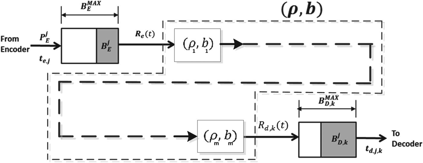
In the following sections, we look at various behavior of compressed video pictures transmitted over the (ρ, b) regulator as shown in Fig. 7. We derive the required buffer size and the desired rate for the (ρ, b) regulator. We also analyze the total equivalent video picture latency and jitter of the (ρ, b) regulator.

Fig. 7. Illustration of (ρ, b) regulators connected in series from the video encoder buffer to the video decoder buffer.
IV. VIDEO DATA BURSTINESS
First, we analyze the burstiness of video data transmitted over the leaky bucket (ρ, b). Consider the compressed video output from the encoder buffer being regulated by a leaky bucket, as shown in Fig. 7, for each picture time interval ![]() $\lsqb t^{\prime}, t^{\prime} +1/f\rsqb $, i.e.,
$\lsqb t^{\prime}, t^{\prime} +1/f\rsqb $, i.e.,
Let us denote the following picture parameters:
• $P_{E}^{MAX}:$ The largest size of a compressed picture within the video sequence (e.g., a movie).
• $P_{E}^{AVG}:$ The average size of a compressed picture within the video sequence (e.g., a movie).
Assume that
and the largest compressed picture ![]() $P_{E}^{MAX}$ of the video sequence can be transmitted within a picture time interval 1/f from the encoder buffer. Note that this assumption is for deriving a lower bound on the token depth of the leaky bucket (ρ, b). However, in practice, this is a general requirement for some video applications.
$P_{E}^{MAX}$ of the video sequence can be transmitted within a picture time interval 1/f from the encoder buffer. Note that this assumption is for deriving a lower bound on the token depth of the leaky bucket (ρ, b). However, in practice, this is a general requirement for some video applications.
Theorem 3
The token depth b of the leaky bucket (ρ, b) needs to satisfy:
Proof: Since the largest compressed picture ![]() $P_{E}^{MAX}$ of the video sequence can be transmitted within a picture time interval 1/f from the encoder buffer, there exists R e (t) at the transmitting time t ′ of the largest compressed picture such that
$P_{E}^{MAX}$ of the video sequence can be transmitted within a picture time interval 1/f from the encoder buffer, there exists R e (t) at the transmitting time t ′ of the largest compressed picture such that
 $$P_E^{MAX} \le \int_{t^{\prime}}^{t^{\prime} +{1 \over f}} R_e (t)dt.$$
Thus, it follows from equation (22) that
Therefore, the inequality equation (21) follows. This completes the proof. □
If the rate ρ is allocated to be equal to the average rate of the compressed video sequence, i.e.,
then
and the entire video (e.g., a movie) can be transmitted within the (time) length of the video.
Inequality equation (21) shows that the required token depth b can be as large as the maximum size of a compressed picture. Inequality equation (23) implies that the burstiness of a compressed video sequence depends not only on the largest compressed picture size, but also on the average compressed picture size.
Traffic shaping is used at the network boundary to provide an average bandwidth between the server and the receiver(s) while keeping the burstiness below a predetermined level. In the following analysis, we will assume that b always satisfies equation (21) and the rate ![]() $R_{e} (t)\le R_{e}^{MAX}$.
$R_{e} (t)\le R_{e}^{MAX}$.
We use ![]() $P_{E}^{MAX} -P_{E}^{AVG}$ as the metric to measure the burstiness of a video stream coded by a given codec, and apply this metric to compare the burstiness levels of three generations of standard video codecs: MPEG-2/H.262, H.264/MPEG-4 AVC, and H.265/MPEG-H HEVC. In particular, we apply this metric to answer the following specific question:
$P_{E}^{MAX} -P_{E}^{AVG}$ as the metric to measure the burstiness of a video stream coded by a given codec, and apply this metric to compare the burstiness levels of three generations of standard video codecs: MPEG-2/H.262, H.264/MPEG-4 AVC, and H.265/MPEG-H HEVC. In particular, we apply this metric to answer the following specific question:
With compression ratios progressively increased and picture sizes (both average and maximum) reduced from MPEG-2 to AVC and from AVC to HEVC, is the worst-case video burstiness also reduced?
Toward answering this question, we make some assumptions about the relative sizes of ![]() $P_{E}^{MAX}$ and
$P_{E}^{MAX}$ and ![]() $P_{E}^{AVG}$ for these three codecs, as summarized in Table 1.
$P_{E}^{AVG}$ for these three codecs, as summarized in Table 1.
Table 1. Burstiness-metric comparisons of MPEG-2, AVC, and HEVC.

In the analysis, MPEG-2 is used as the baseline and compared with AVC and HEVC in terms of burstiness of coded video. For this comparison, it is assumed that, on average,
• The ratio of the maximum MPEG-2 picture size to the average MPEG-2 picture size is a factor α.
• The ratio of the average AVC picture size to the average MPEG-2 picture size is a factor β.
• The ratio of the maximum AVC picture size to the maximum MPEG-2 picture size is a factor γ.
• The ratio of the average HEVC picture size to the average AVC picture size is a factor μ.
• The ratio of the maximum HEVC picture size to the maximum AVC picture size is a factor θ.
The plots in the following diagrams compare the burstiness metric with respect to different values of α, β, γ, θ, and μ. The red and blue lines represent the ratios of HEVC's metric to that of AVC and AVC's metric to that of MPEG-2, respectively.
From Figs 8 and 9, it can be seen that even though the burstiness may be reduced (i.e., burstiness-metric ratio less than 1) for some combinations of α, β, γ, θ, and μ (e.g., with β=μ=0.5, γ=θ=0.6, and α ranging between 2 and 6), the burstiness is barely decreased and even increased (i.e., burstiness-metric ratio larger than 1) for other combinations, e.g., with β=μ=0.5, γ=θ=0.9, and α ranging between 2 and 6. Note that, on average, this combination assumes AVC is 50% more efficient than MPEG-2 and HEVC is 50% more efficient than AVC. However, the efficiency improvement for the largest pictures (e.g., some I-pictures) is only 10%.

Fig. 8. Burstiness-metric comparison (β=μ=0.5, γ=θ=0.6).

Fig. 9. Burstiness-metric comparison (β=μ=0.5, γ=θ=0.9).
The above analysis provides a negative answer to the question posed earlier.
V. RATE
Next, we analyze the service rate offered to a compressed video sequence by a network of ![]() $\lpar \rho_{i} ,b_{i}\rpar , \,i = 1,2,\ldots, m$ regulators in the system shown in Fig. 7. For the system given in Fig. 3, consider all the compressed data in the encoder and the network buffers up to and including picture j right after the time t e, j, i.e., the aggregate buffer fullness is
$\lpar \rho_{i} ,b_{i}\rpar , \,i = 1,2,\ldots, m$ regulators in the system shown in Fig. 7. For the system given in Fig. 3, consider all the compressed data in the encoder and the network buffers up to and including picture j right after the time t e, j, i.e., the aggregate buffer fullness is ![]() $P_{E}^{j} +B_{E}^{j} +B_{N,k}^{j} $. If the equivalent single (ρ(k),b)-regulator is used in the kth video path (as the regulator connected before the decoder buffer shown in Fig. 7), then the rate ρ(k) must satisfy:
$P_{E}^{j} +B_{E}^{j} +B_{N,k}^{j} $. If the equivalent single (ρ(k),b)-regulator is used in the kth video path (as the regulator connected before the decoder buffer shown in Fig. 7), then the rate ρ(k) must satisfy:
to allow all data ![]() $P_{E}^{j} + B_{E}^{j} + B_{N,k}^{j}$ to be transmitted to the decoder buffer before the required decoding time t d, j, k. σk is the integer given in equation (6).
$P_{E}^{j} + B_{E}^{j} + B_{N,k}^{j}$ to be transmitted to the decoder buffer before the required decoding time t d, j, k. σk is the integer given in equation (6).
Lemma 1
The decoder buffer for the kth video path will not underflow if the rate ρ(k) of its input equivalent (ρ(k),b)-regulator satisfies equation (24).
Proof: It can be seen from equations (6) and (24) that
 $$P_E^j + B_E^j + B_{N,k}^j = \int_{t_{e,j}}^{t_{d,j,k}} r_k^{(j)} dt = {c + \sigma_k \over f} \cdot r_k^{(j)}.$$
If we allocate a fixed rate ![]() $R_{d,k} \lpar t \rpar = \rho^{(k)} \ge r_{k}^{(j)} $ for all j, then
$R_{d,k} \lpar t \rpar = \rho^{(k)} \ge r_{k}^{(j)} $ for all j, then
 $$P_E^j +B_E^j +B_{N,k}^j \le \int_{t_{e,j}}^{t_{d,j,k}} R_{d,k} (t)dt.$$
From Theorem 1, this is a sufficient condition for preventing the decoder buffer for the kth video path to underflow. This completes the proof.□
To ensure better network bandwidth utilization, a smaller rate ρ(k) is desirable. To satisfy equation (24), the allocated rate ρ(k) can be as small as
However, this is impractical to calculate.
It is known from the earlier discussion that, for the kth video path, there are c+σk compressed pictures residing in the encoder buffer B E, the network buffer B N, k and the decoder buffer B D, k at the time t e, j for all j, i.e., ![]() $B_{E}^{j},B_{N,k}^{j}$, and
$B_{E}^{j},B_{N,k}^{j}$, and ![]() $B_{D,k}^{j}$ contain exactly c+σk consecutive compressed pictures for all j. Thus, the encoding time t e, j of the jth picture is the decoding time of the
$B_{D,k}^{j}$ contain exactly c+σk consecutive compressed pictures for all j. Thus, the encoding time t e, j of the jth picture is the decoding time of the ![]() $\lpar j-\lpar c+\sigma_{k} \rpar \rpar $-th picture. Since the decoder buffer does not underflow at the decoding time of the
$\lpar j-\lpar c+\sigma_{k} \rpar \rpar $-th picture. Since the decoder buffer does not underflow at the decoding time of the ![]() $\lpar j-\lpar c+\sigma_{k}\rpar \rpar $-th picture,
$\lpar j-\lpar c+\sigma_{k}\rpar \rpar $-th picture, ![]() $B_{D,k}^{j} $ must contain at least one picture, i.e., the
$B_{D,k}^{j} $ must contain at least one picture, i.e., the ![]() $\lpar j-\lpar c+\sigma_{k} \rpar \rpar $-th picture. Therefore,
$\lpar j-\lpar c+\sigma_{k} \rpar \rpar $-th picture. Therefore, ![]() $B_{E}^{j} +B_{N,k}^{j} $ must contain, at most,
$B_{E}^{j} +B_{N,k}^{j} $ must contain, at most, ![]() $c+\sigma_{k} -1$ pictures, and
$c+\sigma_{k} -1$ pictures, and
 $${f \over c + \sigma_k} \lpar P_E^j + B_E^j + B_{N,k}^j \rpar \le {f \over c + \sigma_k} \cdot \sum_{i = 0}^{c + \sigma_k - 1} P_E^{j-i} ,\forall j.$$
Therefore, we can allocate the rate ρ(k) for the kth video path to be
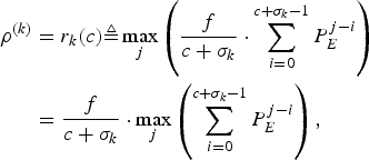 $$\eqalign{\rho^{(k)}& = r_k (c) \triangleq \max_j \left({f \over c+\sigma_k} \cdot \sum_{i = 0}^{c + \sigma_k - 1} P_E^{j-i}\right) \cr & = {f \over c + \sigma_k} \cdot \max_j \left(\sum_{i = 0}^{c + \sigma_k -1} P_E^{j-i} \right),}$$
i.e., the allocated rate ![]() $\rho^{(k)}=r_{k} (c)$ is the maximum value of the average rates of a sliding window of c+σk consecutive compressed pictures of the video sequence. Note that
$\rho^{(k)}=r_{k} (c)$ is the maximum value of the average rates of a sliding window of c+σk consecutive compressed pictures of the video sequence. Note that ![]() $r_{k} \lpar c \rpar $ is not only dependent on the video sequence parameters (i.e., compressed sizes P Ei and the picture rate f), but also the network delay parameter σk.
$r_{k} \lpar c \rpar $ is not only dependent on the video sequence parameters (i.e., compressed sizes P Ei and the picture rate f), but also the network delay parameter σk.
Lemma 2
The decoder buffer for the kth video path will not overflow if the rate ρ(k) of its input equivalent (ρ(k),b) regulator satisfies equation (26).
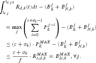
Proof: For the rate ρ(k) satisfies equation (29), we can have ![]() $R_{d,k} (t)=\rho^{(k)}$. From equations (8), (10), (18), and (26), we obtain
$R_{d,k} (t)=\rho^{(k)}$. From equations (8), (10), (18), and (26), we obtain
 $$\eqalign{&\int_{t_{e,j}}^{t_{d,j,k}} R_{d,k} \lpar t \rpar dt - (B_E^j +B_{N,k}^j) \cr &\quad = \max_j \left(\sum_{i = 0}^{c + \sigma_k -1} P_E^{j - i} \right) - (B_E^j + B_{N,k}^j) \cr &\quad \le \lpar c + \sigma_k \rpar \cdot P_E^{MAX} - (B_E^j + B_{N,k}^j) \cr &\quad \le {c + \sigma_k \over f} \cdot R_{e,d,k}^{MAX} = B_{D,k}^{MAX} ,\forall j.}$$
From Theorem 2, this is a sufficient condition for preventing the decoder buffer for the kth video path to overflow. This completes the proof. □
The following main result follows from Lemmas 1 and 2:
Theorem 4
The decoder buffer for the kth video path will neither underflow nor overflow if the rate ρ(k) of its input equivalent (ρ(k),b) regulator satisfies equation (29).
Note: Comparing with ρavg in equation (22), the rate ρ(k) in equation (26) is a different result. While the rate ρavg implies that the entire video can be sent over the (time) length of the video, the rate ρ(k) ensures any c+σk consecutive compressed pictures can be transmitted over the c+σk picture time interval ![]() $c + \sigma_{k} /f$.
$c + \sigma_{k} /f$.
For the system model given in Fig. 5, i.e., the network link for the kth video path between the output of the encoder buffer and the input of the decoder buffer has a fixed delay Δk/f with a jitter δk/f, we can prove the following theorem.
Theorem 5
For the video transmission system model given in Fig. 5, the decoder buffer with a size ![]() $\bar{B}_{D}^{MAX}(\delta_{k})$ given in equation (15) for the kth video path will neither underflow nor overflow if the rate ρ of its input equivalent (ρ, b) regulator satisfies
$\bar{B}_{D}^{MAX}(\delta_{k})$ given in equation (15) for the kth video path will neither underflow nor overflow if the rate ρ of its input equivalent (ρ, b) regulator satisfies ![]() $\rho = {f \over c} \cdot \max_{j} \left(\sum\nolimits_{i=0}^{c-1} P_{E}^{j-i} \right)$.
$\rho = {f \over c} \cdot \max_{j} \left(\sum\nolimits_{i=0}^{c-1} P_{E}^{j-i} \right)$.
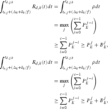
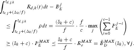
Proof: Follows directly from equations (6), (13–15), and (20),
 $$\eqalign{\int_{t_{e,j} + (\Delta_k + \delta_k /f)}^{t_{d,j,k}} R_{d,k} (t)dt & = \int_{t_{e,j} + (\Delta_k + \delta_k /f)}^{t_{d,j,k}} \rho dt \cr & = \max_j \left(\sum_{i=0}^{c-1} P_E^{j-i} \right) \cr &\ge \sum_{i = 0}^{c - 1} P_E^{j - i} \ge P_E^j +B_E^j, \cr \int_{t_{e,j} +(\Delta_k +\delta_k /f)}^{t_{d,j,k}} R_{d,k} (t)dt &= \int_{t_{e,j} + (\Delta_k + \delta_k /f)}^{t_{d,j,k}} \rho dt \cr & = \max_j \left(\sum_{i = 0}^{c - 1} P_E^{j - i} \right) \cr &\ge \sum_{i = 0}^{c - 1} P_E^{j - i} \ge P_E^j + B_E^j,}$$
and
 $$\eqalign{&\int_{t_{e,j} +(\Delta_k /f)}^{t_{d,j,k}} R_{d,k} \lpar t \rpar dt-B_E^j\cr &\quad \le \int_{t_{e,j} +(\Delta_k /f)}^{t_{d,j,k}} \rho dt={\lpar \delta_k +c \rpar \over f}\cdot {f \over c}\cdot \max_j \left( \sum_{i=0}^{c-1} P_E^{j-i}\right) \cr &\quad \ge \lpar \delta_k +c \rpar \cdot P_E^{MAX} \le {\delta_k +c \over f}\cdot R_e^{MAX} =\bar{B}_D^{MAX}(\delta_k), \forall j.}$$
Therefore, from Corollary 2, the decoder buffer for the kth video path will neither underflow nor overflow. This completes the proof. □
Note: The rate ![]() $\rho = f/c \cdot \max_{j} \left(\sum\nolimits_{i = 0}^{c - 1} P_{E}^{j - i}\right)$ is now only a function of the video parameters, and is independent of network delay and jitter of the kth video path. However, the decoder buffer size is a jitter-dependent parameter for the kth video path.
$\rho = f/c \cdot \max_{j} \left(\sum\nolimits_{i = 0}^{c - 1} P_{E}^{j - i}\right)$ is now only a function of the video parameters, and is independent of network delay and jitter of the kth video path. However, the decoder buffer size is a jitter-dependent parameter for the kth video path.
For the video transmission system model given in Fig. 6, we can derive the following theorem.
Theorem 6
For the video transmission system model given in Fig. 6, the decoder buffer for the kth video path will neither underflow nor overflow if the rate ρ of its input equivalent (ρ, b) regulator satisfies ![]() $\rho = f/c\cdot \max_{j} \left(\sum\nolimits_{i = 0}^{c - 1} P_{E}^{j - i} \right)$.
$\rho = f/c\cdot \max_{j} \left(\sum\nolimits_{i = 0}^{c - 1} P_{E}^{j - i} \right)$.
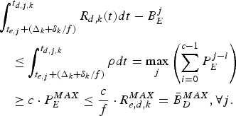
Proof: Follows directly from equations (4), (16), (17), and (20),
 $$\eqalign{\int_{t_{e,j} + {\Delta_k +\delta_k \over f}}^{t_{d,j,k}} R_{d,k} (t) dt &= \int_{t_{e,j} + {\Delta_k +\delta_k \over f}}^{t_{d,j,k}} \rho dt = \max_j \left(\sum_{i = 0}^{c - 1} P_E^{j - i} \right) \cr &\ge \sum_{i = 0}^{c - 1} P_E^{j - i} \ge P_E^j + B_E^j}$$
and
 $$\eqalign{&\int_{t_{e,j} +(\Delta_k +\delta_k /f)}^{t_{d,j,k}} R_{d,k} (t)dt-B_E^j \cr &\quad \le \int_{t_{e,j} +(\Delta_k +\delta_k /f)}^{t_{d,j,k}} \rho dt = \max_j \left(\sum_{i = 0}^{c - 1} P_E^{j - i}\right) \cr &\quad \ge c \cdot P_E^{MAX} \le {c \over f} \cdot R_{e,d,k}^{MAX} = \bar{B}_D^{MAX}, \forall j.}$$
Therefore, from Corollary 3, the decoder buffer for the kth video path will neither underflow nor overflow. This completes the proof. □
It can be seen that, from the perspective of decoding time and total buffer sizes, Theorem 5 is equivalent to Theorem 6. Also the system model shown in Fig. 4 is a special case of the system model given in Fig. 6 with δk=0. It is easy to verify that ![]() $\rho = f/c \cdot \max_{j} \left(\sum\nolimits_{i = 0}^{c - 1} P_{E}^{j - i} \right)$ given in Theorem 6 also satisfies the rate conditions of Corollary 1. Thus, we have
$\rho = f/c \cdot \max_{j} \left(\sum\nolimits_{i = 0}^{c - 1} P_{E}^{j - i} \right)$ given in Theorem 6 also satisfies the rate conditions of Corollary 1. Thus, we have
Corollary 4
If the network link for the kth video path has a fixed delay between the output of the encoder buffer and the input of the decoder buffer at t ò T for all pictures, the decoder buffer with a size ![]() $\bar{B}^{MAX}_{D}$ given in equation (4) will neither underflow nor overflow if the rate ρ of its input equivalent (ρ, b) regulator satisfies
$\bar{B}^{MAX}_{D}$ given in equation (4) will neither underflow nor overflow if the rate ρ of its input equivalent (ρ, b) regulator satisfies ![]() $\rho = f/c \cdot \max_{j} \left(\sum\nolimits_{i = 0}^{c - 1} P_{E}^{j - i} \right)$.
$\rho = f/c \cdot \max_{j} \left(\sum\nolimits_{i = 0}^{c - 1} P_{E}^{j - i} \right)$.
Once again, the rate ![]() $\rho = f/c \cdot \max_{j} \left(\sum\nolimits_{i = 0}^{c - 1} P_{E}^{j - i} \right)$ is only a function of the video parameters, and is independent of network delay and jitter of the kth video path. In this case, the actual decoder buffer size is now independent of network jitter.
$\rho = f/c \cdot \max_{j} \left(\sum\nolimits_{i = 0}^{c - 1} P_{E}^{j - i} \right)$ is only a function of the video parameters, and is independent of network delay and jitter of the kth video path. In this case, the actual decoder buffer size is now independent of network jitter.
VI. END-TO-END TRANSMISSION DELAY AND NETWORK JITTER
In the analysis so far, it is assumed that each compressed picture is a single integral entity (e.g., modeled as an impulse function) when it traverses the IP network. With this assumption, there is no ambiguity about picture-related timings. In this section, we relax the above assumption with respect to the practical IP networks, where each video picture is transmitted as a sequence of packets (e.g., Ehternet frames). We define the picture-related timings for packetized video transmission. Furthermore, we establish the delay and jitter bounds for a class of IP networks.
In practice, before the video stream is transmitted to the IP network, the pictures are first packetized on the encoder side. The video packets are then transmitted over the IP network, which in general, consists of a series of routers and switches. On the decoder side, the received video packets, which may be out of order during transit, are reordered and depacketized to reassemble original compressed pictures as the input to the decoder bufferFootnote 5. Figure 10 represents a given video path in Fig. 2.

Fig. 10. Transmission of packetized video pictures.
As shown in Fig. 11, on the encoder side, the pictures are modeled as impulse functions at both the input and output of the encoder buffer. The picture ![]() $P_{E}^{j} $ is packetized and transmitted to the IP network as a sequence of N j packets of sizes
$P_{E}^{j} $ is packetized and transmitted to the IP network as a sequence of N j packets of sizes ![]() $L_{j,1} ,L_{j,2}, \ldots, L_{j,N_{j}} $ at instances
$L_{j,1} ,L_{j,2}, \ldots, L_{j,N_{j}} $ at instances ![]() $T_{e,j,1} ,T_{e,j,2} ,\ldots, T_{e,j,N_{j}}$, respectively, where
$T_{e,j,1} ,T_{e,j,2} ,\ldots, T_{e,j,N_{j}}$, respectively, where ![]() $T_{e,j,1} \le T_{e,j,2} \le \cdots \le T_{e,j,N_{j}}$. Assume that the packetizer starts the packetization of the first packet of the picture
$T_{e,j,1} \le T_{e,j,2} \le \cdots \le T_{e,j,N_{j}}$. Assume that the packetizer starts the packetization of the first packet of the picture ![]() $P_{E}^{j}$ at instance
$P_{E}^{j}$ at instance ![]() $T_{e,j,0} \lt T_{e,j,1}$. After traversing the IP network, these packets are received on the decoder side at instances
$T_{e,j,0} \lt T_{e,j,1}$. After traversing the IP network, these packets are received on the decoder side at instances ![]() $T_{d,j,1} ,T_{d,j,2} , \ldots, T_{d,j,N_{j}}$, probably out of order. They are then reordered and depacketized into the original picture
$T_{d,j,1} ,T_{d,j,2} , \ldots, T_{d,j,N_{j}}$, probably out of order. They are then reordered and depacketized into the original picture ![]() $P_{E}^{j}$, which is pushed into the decoder buffer before being decoded for display at t d, j, k.
$P_{E}^{j}$, which is pushed into the decoder buffer before being decoded for display at t d, j, k.

Fig. 11. Timings for the transmission of packetized video pictures.
In the following, we first establish the general delay and jitter bounds for the pictures transmitted over the above IP network.
On the encoder side, we assume that the packetization of a video picture starts immediately after the picture is input to the packetizer and that the transmission of the first packet of a video picture takes place once the packet is available to the transmitter. Therefore, the time at which the jth picture is output from the encoder buffer, ![]() $t_{e,j}^{\prime} $, coincides with the time when the first packet of the picture starts to be packetized, T e, j, 0; that is,
$t_{e,j}^{\prime} $, coincides with the time when the first packet of the picture starts to be packetized, T e, j, 0; that is,
On the decoder side, we assume that when the last packet of the picture j is received and made available to the depacketizer, the reordering and depacketization of the picture will be completed immediately. Therefore, the time at which the jth picture is input into the decoder buffer coincides with the time at which the last packet of the picture is received from the IP network; that is,
Then, the end-to-end delay of the jth picture for the kth video path across the IP network can be denoted as
Assume that the maximum latency for any picture to go through the Packetizer and Transmitter is T p; that is,
Then, for any j and any i with 1≤i≤N j,
Furthermore, assume that the maximum delay for any video packet to traverse the kth video path of the IP network is D k; that is,
Thus, for any j and any i with 1≤i≤N j,
Then we have the following result:
Lemma 3
The maximum end-to-end delay of video pictures across kth video path of the IP network is upper-bounded as follows:
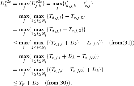
Proof: From the definitions of ![]() $D_{k}^{e2e}$ in equation (32) and
$D_{k}^{e2e}$ in equation (32) and ![]() $D_{j,k}^{e2e}$ given in equation (29),
$D_{j,k}^{e2e}$ given in equation (29),
 $$\eqalign{D_k^{e2e} &= \max_j \lcub D_{j,k}^{e2e} \rcub = \max_j \lcub t^{\prime}_{d,j,k} -t^{\prime}_{e,j} \rcub \cr &= \max_j \lcub \max_{1\le i\le N_j} \{T_{d,j,i} \} - T_{e,j,0} \rcub \cr & = \max_j \lcub \max_{1\le i\le N_j} \{T_{d,j,i} - T_{e,j,0} \} \rcub \cr &\le \max_j \lcub \max_{1\le i\le N_j} \lcub \{T_{e,j,i} +D_k \} - T_{e,j,0} \rcub \rcub \quad (\hbox{from} (31)) \cr &= \max_j \lcub \max_{1\le i\le N_j } \lcub T_{e,j,i} +D_k -T_{e,j,0} \rcub \rcub \cr &=\max_j \lcub \max_{1\le i\le N_j } \lcub (T_{e,j,i} -T_{e,j,0} )+D_k \rcub \rcub \cr &\le T_p +D_k \quad (\hbox{from} (30)).}$$
This completes the proof. □
Note that the above theorem holds even for the cases where packet reordering is performed by the Receiver and Depacketizer.
In [Reference Stiliadis and Varma4], the latency of a general class of routers is modeled and analyzed in detail. Here, we will apply the result obtained from [Reference Stiliadis and Varma4] to derive a delay upper bound for our video transmission model.
For the kth video path, if the input video stream is (ρ, b)-regulated, the maximum delay D k incurred by a packet traversing an IP network that consists of s k routersFootnote 6 is upper-bounded by
 $$D_k \le {b \over \rho} + \sum_{i = 1}^{s_k} \Theta_{i,k} + \sum_{i = 1}^{s_k} p_{i,k},$$
where Θi, k is the latency of the ith router along the kth video path and p i, k is the propagation delay between the ith router and its next neighboring node along the kth video path. Each router has the rate at least ρ.
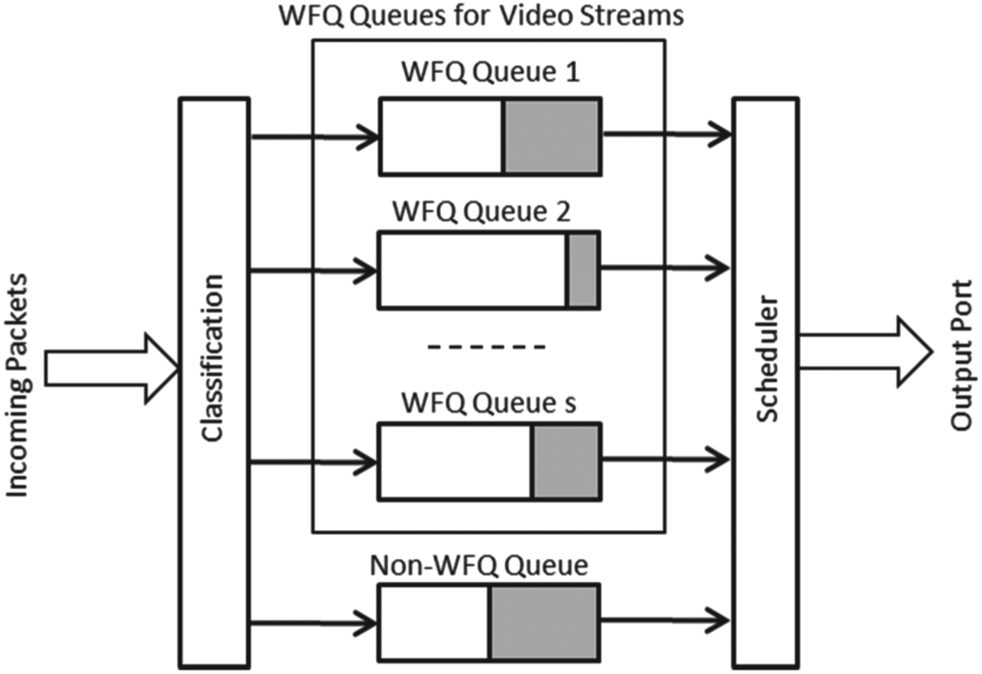
To make the analysis concrete, consider the cases where each router along the video path is modeled as a Weighted Fair Queuing (WFQ) system. Such cases exist in practice, since many deployed routers indeed support WFQ for their rate shaping and scheduling functions [11,12]. A high-level diagram for a WFQ system is illustrated in Fig. 12, where the incoming packets are classified into their corresponding queues that represent different data streams and multiple WFQ queues, and a non-WFQ queue share the bandwidth of the output port. Usually, the WFQ queues are guaranteed by the scheduler a minimum percentage (e.g., 70%) of the total output port bandwidth, and in turn, the scheduler guarantees a given average data rate for each WFQ queue based on its weight. The average data rate for each WFQ queue can be dynamically configured via a QoS-negotiation protocol such as Resource Reservation Protocol.

Fig. 12. IP Router Modeled as WFQ.
As shown in [Reference Stiliadis and Varma4], if the ith router (i<s k) can be modeled as a WFQ system, then its latency is given by
where ![]() $L_{k,max}$ is the maximum packet size of the kth video stream (which is sent along the kth video path),
$L_{k,max}$ is the maximum packet size of the kth video stream (which is sent along the kth video path), ![]() $L_{max,i}$ is the maximum packet size among all streams sent to the ith router, and r i is the total bandwidth of the output port of the ith router. For the last router (the s k -th), if it can be modeled as a WFQ system, its latency is given by [Reference Stiliadis and Varma4]
$L_{max,i}$ is the maximum packet size among all streams sent to the ith router, and r i is the total bandwidth of the output port of the ith router. For the last router (the s k -th), if it can be modeled as a WFQ system, its latency is given by [Reference Stiliadis and Varma4]
If all s k routers in Fig. 10 can be modeled as WFQ systems, from equations (33), (34), and (35), the total delay incurred by a packet of the kth stream across this network, D k, is upper-bounded as
 $$D_k \le {b \over \rho} + \lpar s_k - 1 \rpar \times {L_{k,max} \over \rho} + \sum_{i = 1}^{s_k} {L_{max,i} \over r_i} + \sum_{i = 1}^{s_k} p_{i,k}.$$
Thus, Lemma 4 and Theorem 7 directly follow from Lemma 3, equations (36) and (6).
Lemma 4
For an IP network with the (ρ, b)-regulated video input and s k WFQ routers along the kth video path, the maximum end-to-end delay of video pictures across the video path is bounded by
 $$\eqalign{& D_{j,k}^{e2e} \le T_p + D_k \le T_p \cr & \quad + \left[{b \over \rho} + \lpar s_k - 1 \rpar \times {L_{k,max} \over \rho} + \sum_{i = 1}^{s_k} {L_{max,i} \over r_i} + \sum_{i = 1}^{s_k} p_{i,k} \right].}$$
Theorem 7
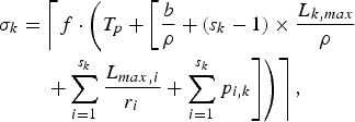
For an IP network with the (ρ, b)-regulated video input and s k WFQ routers along the k-th video path, the network buffer delay parameter σk defined in equation (6) can be set to
 $$\eqalign{\sigma_k & = \left\lceil f \cdot \left(T_p + \left[{b \over \rho} + \lpar s_k - 1 \rpar \times {L_{k,max} \over \rho} \right. \right. \right. \cr &\left. \left. \left. \quad + \sum_{i = 1}^{s_k} {L_{max,i} \over r_i} + \sum_{i = 1}^{s_k} p_{i,k} \right] \right) \right\rceil,}$$
where ![]() $\lceil. \rceil $ denotes the ceiling function.
$\lceil. \rceil $ denotes the ceiling function.
We can also split the network buffer delay parameter σk into a fixed delay parameter Δk and a maximum jitter parameter δk, as exemplified in the corollary below.
Corollary 5
For an IP network with the (ρ, b)-regulated video input and s k WFQ routers along the kth video path, the network buffer delay parameter σk may be set to ![]() $\sigma_{k} = \Delta_{k} +\delta_{k}$ with
$\sigma_{k} = \Delta_{k} +\delta_{k}$ with
 $$\Delta_k = \left\lfloor f \cdot \left( \lpar s_k - 1 \rpar \times {L_{k,min} \over \rho} + \sum_{i = 1}^{s_k} p_{i,k} \right) \right\rfloor,$$
where ![]() $\lfloor. \rfloor$ denotes the floor function and L k, min is the minimum packet size of the video being sent along the kth video path, and
$\lfloor. \rfloor$ denotes the floor function and L k, min is the minimum packet size of the video being sent along the kth video path, and
 $$\eqalign{\delta_k & = \left\lceil f\cdot \left(T_p + {b \over \rho} + \lpar s_k - 1 \rpar \right. \right. \cr &\left. \left. \quad \times {(L_{k,max} - L_{k,min}) \over \rho } + \sum_{i = 1}^{s_k} {L_{max,i} \over r_i} \right) \right\rceil + 1.}$$
It is easy to show that the network buffer delay parameter σk in Corollary 5 is larger than or equal to the one in Theorem 7.
As one can see from equations (39) and (40), the fixed delay parameter Δk is determined by the overall minimum packet latency over routers in the kth video path and the total propagation delay, while the maximum jitter parameter δk is determined by the latency from video stream burstiness (over the transmission rate), the latency from packetization and serialization, and the overall packet jitter over routers in the kth video path caused by all streams.
In the following examples, Δk and δk are calculated for a video transmitted in its average rates ρavg defined in equation (22) and ρ* set according to Theorem 5.
1) Packetization and serialization latency T p
This represents the latency incurred by a video picture going through the Packetizer and Transmitter. It is measured between the time when the video picture is made available to the packetizer (the time that the packetization of the first packet of the picture starts) and the time when the last packet of the picture is completely transmitted to the IP network. Thus, it includes the latency of the packetization process as well as the latency for the serialized transmission of packets.
2) Video burst duration
The ratio of maximum burst size b and the average data rate ρ represents the burst duration when the video is transmitted across an IP network. From Theorem 3 and equation (26), we can use ![]() $(P_{E}^{MAX} -P_{E}^{AVG})$ to approximate the maximum burst size b. For the choice of the average data rate ρ, we have two options: (a) the data rate ρavg defined in equation (22); (b) the data rate ρ* that is set according to Theorem 5. The video burst duration is then calculated by
$(P_{E}^{MAX} -P_{E}^{AVG})$ to approximate the maximum burst size b. For the choice of the average data rate ρ, we have two options: (a) the data rate ρavg defined in equation (22); (b) the data rate ρ* that is set according to Theorem 5. The video burst duration is then calculated by ![]() $(P_{E}^{MAX} - P_{E}^{AVG})/\rho_{avg} = (P_{E}^{MAX} - P_{E}^{AVG})/(P_{E}^{AVG} \times f)$ and
$(P_{E}^{MAX} - P_{E}^{AVG})/\rho_{avg} = (P_{E}^{MAX} - P_{E}^{AVG})/(P_{E}^{AVG} \times f)$ and ![]() $(P_{E}^{MAX} - P_{E}^{AVG})/\rho^{\ast}$, for the two options of average data rate, respectively. Following the same method of determining the relative sizes of maximum and average pictures with respect to different codecs as in Table 1, we compare the video burst durations for MPEG-2, AVC and HEVC in Table 2, with the assumption that
$(P_{E}^{MAX} - P_{E}^{AVG})/\rho^{\ast}$, for the two options of average data rate, respectively. Following the same method of determining the relative sizes of maximum and average pictures with respect to different codecs as in Table 1, we compare the video burst durations for MPEG-2, AVC and HEVC in Table 2, with the assumption that ![]() $\rho^{\ast} = \rho_{avg} \times \omega$, for a factor ω.
$\rho^{\ast} = \rho_{avg} \times \omega$, for a factor ω.
Table 2. Burst-duration comparisons of MPEG-2, AVC, and HEVC.

The burst durations of MPEG-2, AVC, and HEVC are plotted in Figs 13 and 14 with respect to different values of α for ![]() $\beta = \mu = 0.5,\;\gamma = \theta = 0.9,$ and ω=1.2. Figures 13 and 14 are for options (a) and (b) of average data rate, respectively.
$\beta = \mu = 0.5,\;\gamma = \theta = 0.9,$ and ω=1.2. Figures 13 and 14 are for options (a) and (b) of average data rate, respectively.

Fig. 13. Burst duration comparisons of MPEG-2, AVC, HEVC (β=μ=0.5, γ=θ=0.9).

Fig. 14. Burst-duration comparisons of MPEG-2, AVC, HEVC (β=μ=0.5, γ=θ=0.9, ω=1.2).
As can be seen from the plots, MPEG-2, AVC, and HEVC have progressively higher burst durations, for both options of average data rate.
3) Router queuing delay
This delay is represented by ![]() $\lpar s_{k} -1\rpar \times L_{k,max} /\rho _{k} + \sum\nolimits_{i = 1}^{s_{k}} L_{max,i} /r_{i}$ and depends on the average data rate of the video stream (ρk), the number of routers (i.e., hops) along the kth video path (s k), the maximum packet size of the kth stream
$\lpar s_{k} -1\rpar \times L_{k,max} /\rho _{k} + \sum\nolimits_{i = 1}^{s_{k}} L_{max,i} /r_{i}$ and depends on the average data rate of the video stream (ρk), the number of routers (i.e., hops) along the kth video path (s k), the maximum packet size of the kth stream ![]() $(L_{k,max})$, the maximum packet size among all streams
$(L_{k,max})$, the maximum packet size among all streams ![]() $(L_{max,i})$ and the total bandwidth of the output port (r i) for the ith router. A typical hop count for an Internet connection within U.S. domains is 14 [Reference Fei, Pei, Liu and Zhang13]. The maximum Ethernet packet size is 1518 bytes; so we can set both
$(L_{max,i})$ and the total bandwidth of the output port (r i) for the ith router. A typical hop count for an Internet connection within U.S. domains is 14 [Reference Fei, Pei, Liu and Zhang13]. The maximum Ethernet packet size is 1518 bytes; so we can set both ![]() $L_{k,max}$ and
$L_{k,max}$ and ![]() $L_{max,i}$ to be 1518 bytes. Then, with the assumptions that
$L_{max,i}$ to be 1518 bytes. Then, with the assumptions that ![]() $\rho_{k} = 20\,\hbox{Mbps}$ (e.g., for 4 K HEVC video) and r i=100 Mbps, the router queuing delay is
$\rho_{k} = 20\,\hbox{Mbps}$ (e.g., for 4 K HEVC video) and r i=100 Mbps, the router queuing delay is  $\lpar s_{k} - 1\rpar \times L_{k,max} /\rho_{k} +\sum_{i = 1}^{s_{k}} L_{max,i} /r_{i} = \lpar 14 - 1 \rpar \times {1518 \times 8 \over 20 \times 1000} + 14\times {1518\times 8 \over 100 \times 1000} = 7.9 + 1.7 \approx 10\,\hbox{ms}$.
4) Total propagation delay
This delay depends on the distances and media types of the links connecting all routers along the video path. For terrestrial fiber links totaling 4800 km (roughly the coast-to-coast continental U.S. distance), the total propagation delay is 4800/(300×0.7)≈23 ms, assuming a light speed of 300 km/ms and a velocity factor of 0.7 for optical fiber. Similarly, for MEO and GEO satellite links of 18 000 and 74 000 km, the corresponding delays are 60 and 247 ms, respectively.
The following table summarizes some examples for Δk and δk.
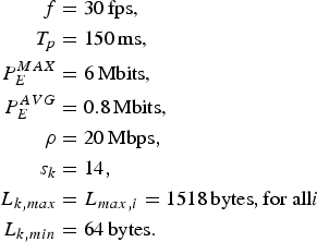
In the above table, it is assumed that
 $$\eqalign{f&=30\,\hbox{fps,}\cr T_p &=150\,\hbox{ms,}\cr P_E^{MAX} &=6\,\hbox{Mbits,} \cr P_E^{AVG} &=0.8\,\hbox{Mbits,}\cr \rho &=20\,\hbox{Mbps}, \cr s_k & = 14, \cr L_{k,max} & = L_{max,i} = 1518\,\hbox{bytes}, \hbox{for all} i \cr L_{k,min} & = 64\,\hbox{bytes}.}$$
Fiber links U.S.-to-U.S.: 4800 km fiber links with velocity factor of 0.7
Fiber links U.S.-to-China: 11 500 km fiber links with velocity factor of 0.7
MEO Satellite: 18 000 km, with terrestrial segment of the propagation delay ignored
GEO Satellite: 74 000 km, with terrestrial segment of the propagation delay ignored
In the above examples, the dominating component of the fixed delay ![]() $(\Delta _{k} /f)$ is the total propagation delay, and the dominating components of the maximum jitter
$(\Delta _{k} /f)$ is the total propagation delay, and the dominating components of the maximum jitter ![]() $(\delta_{k} /f)$ are the packetization and serialization latency and the burst duration. In comparison, the contribution of router queuing to the fixed delay and the maximum jitter is relatively very small. As can be seen from Figs 13 and 14, MPEG-2, AVC, and HEVC have progressively higher burst durations, with the burst duration almost doubling from one generation of video codec to the next. Therefore, for a given video data path, the maximum jitter can be substantially increased across the streams (or programs) that are coded with these three generations of video codecs. This can potentially impact the user's channel-changing experience (e.g., when the user switches between a Standard Definition program coded with MPEG-2 and the same program of High Definition coded with AVC).
$(\delta_{k} /f)$ are the packetization and serialization latency and the burst duration. In comparison, the contribution of router queuing to the fixed delay and the maximum jitter is relatively very small. As can be seen from Figs 13 and 14, MPEG-2, AVC, and HEVC have progressively higher burst durations, with the burst duration almost doubling from one generation of video codec to the next. Therefore, for a given video data path, the maximum jitter can be substantially increased across the streams (or programs) that are coded with these three generations of video codecs. This can potentially impact the user's channel-changing experience (e.g., when the user switches between a Standard Definition program coded with MPEG-2 and the same program of High Definition coded with AVC).
VII. SYSTEM TIMING
We have analyzed several models of video transmission systems and proved theorems and corollaries for these models regarding the required conditions for video network transmission rates, buffer dynamics, and picture coding times. To ensure the encoder and the decoder operate properly in these models, we must also have an appropriate clock to drive the system timing. In this section, we will discuss the processes of generating system timing and their impacts on video transmission over the network and derivation of various picture timing parameters, such as t d, j, k.
There are two primary approaches to provide the system timing: the encoder clock and the global clock.
A) Encoder clock
The encoder clock is a time source in the encoder that serves as the master timing source for the encoder, and is also used for generating slave timing sources for the network and the decoder(s). For example, in MPEG-2 systems, the 27 MHz System Time Clock (STC) drives the encoding process and is also used as a “master clock” for the entire video transmission system. At the encoder end, the Decode Time Stamp (DTS) and the Presentation Time Stamp (PTS) are created from the STC and carried together with the video packets. The DTS tells the decoder when to decode the picture, while the PTS tells the decoder when to display the picture.
In addition to knowing the time decoding and presentation should occur, the STC clock samples are also embedded, to allow a time reference to be created. The Program Clock Reference (PCR) in MPEG-2 Transport Stream (TS) provides 27 MHz clock recovery information. PCR is a clock recovery mechanism for MPEG programs. In MPEG-2 TS, when a video is encoded, a 27 MHz STC drives the encoding process. When the program is decoded (or re-multiplexed), the decoding process is driven by a clock that is locked to the encoder's STC.
The decoder uses the PCR to regenerate a local 27 MHz clock. As mentioned above, when a compressed video is inserted into the MPEG-2 TS, a 27 MHz PCR timestamp is embedded. At the decoder end, it uses a Voltage Controlled Oscillator (VCXO) to generate a 27 MHz clock. When a PCR is received, it is compared to a local counter, which is driven by the VCXO, and the difference is used to correct the frequency of the VCXO, so that the 27 MHz clock is locked to the PCR. Then, the decoding and presentation processes happen at the mature DTS and PTS times, respectively.
In this approach, all time stamps (including the clock reference) are carried with the video packets and transmitted from the encoder end to the decoder end. Thus, we don't need to know the exact network delay to generate these time stamps since the clock is locked to the encoder clock and the actual decoding time has counted for the DTS packets network delay, e.g., ![]() $t_{d,j,k} = \Delta_{k} /f + DTS_{j}$ for the system given in Fig. 4, and
$t_{d,j,k} = \Delta_{k} /f + DTS_{j}$ for the system given in Fig. 4, and
for the system given in Fig. 6. However, this approach requires that the network has a constant delay at the time stamp extraction point. Therefore, this approach is clearly suitable to the video transmission systems given by Figs 4 and 6, but would not work correctly for the system shown in Fig. 5.
B) Global clock
This is a global time source (e.g., synchronized “wall clock”) for the encoder and the decoder. For example, both the encoder and the decoder can use a precise global clock, e.g., GPS clock, to generate, compare, and calculate all encoding, decoding, and presentation timing parameters, and to drive the timing circuits for the encoding and decoding systems. In this approach, the DTS and PTS are also carried with the video packets and transmitted from the encoder to the decoder. For example, t d, j, k given in equation (41) is also applicable for the system given in Fig. 5 (as long as the DTS are extracted and used before the decoding time).
If a global clock is available, this approach is generally applicable to all video transmission systems, including those described by the above figures and theorems.
It is easy to see that the two approaches discussed here for generating system timing and driving the decoding and presentation processes can be equivalent to each other.
VIII. VIDEO SERVICE TYPES
We will discuss three video service types here: unicast, broadcast, and multicast.
A) Video unicast
Video unicast is a network communication where a video is sent from just one sender to one receiver, e.g. a video packet is sent from a single source to a specified destination. Today, unicast transmission is still the predominant form of video transmission over the Internet and on local area networks (LANs). Examples include YouTube video transmission and Netflix video service. All IP networks support the unicast transfer mode, and most users are familiar with the standard unicast applications (e.g., HTTP, SMTP, FTP, and Telnet) which employ the TCP transport protocol. All systems and theorems discussed above can be used to video unicast applications.
B) Video broadcast
Video broadcast is a network communication where a video is sent from one point to all other service points. In this case, there is just one server, but the video is sent to all connected receivers for the service. Video broadcast examples include cable and satellite digital Pay-TV broadcasting services. Today, these service examples are still the predominant forms of high-quality and carrier-grade video services to hundreds of millions of homes. Broadcast transmission is supported on most of IP networks. Network layer protocols, such as IPv4, support a form of broadcast that allows the same packet to be sent to every system in a logical network (in IPv4, this consists of the IP network ID and an all 1’s host number).
In the traditional cable and satellite video broadcast services, the transmission propagation delay differences among all receivers are usually negligible. Thus, if we consider the system model given in Fig. 4, the delay is the same for all video paths, i.e., ![]() $\Delta = \Delta_{k} = \hbox{constant}$ for all k. Therefore, in this case, the decoding time for each picture is the same for receivers on all video paths, i.e.,
$\Delta = \Delta_{k} = \hbox{constant}$ for all k. Therefore, in this case, the decoding time for each picture is the same for receivers on all video paths, i.e., ![]() $t_{d,j} = \Delta /f+ {DTS}_{j}$.
$t_{d,j} = \Delta /f+ {DTS}_{j}$.
When video programs are streaming over an IP network, the transmission delays are different for each receiver due to network delay differences at various nodes. However, it can be seen from the example in Table 3 that, for the system models given in Figs 5 and 6, the decoding time t d, j, k differences among different video paths, i.e., receivers at different network nodes, may not be significant enough to cause user-experience issues for some real-time video programs, e.g., real-time sport events.
Table 3. Examples on various delays and fixed delay parameter and maximum jitter parameter.

If the service aims to achieve the same decoding time, then a DTS offset would need to be added at each decoding path. In the systems given by Figs 5 and 6, for example, we can use ![]() $\bar{\Delta} = \max_{k} \lpar \Delta_{k} +\delta_{k} \rpar $ for all receivers in the service network. We can also use
$\bar{\Delta} = \max_{k} \lpar \Delta_{k} +\delta_{k} \rpar $ for all receivers in the service network. We can also use ![]() $\overline{\bar{B}}_{D}^{MAX} =\max_{k} \lpar \bar{B}_{D}^{MAX}\rpar $ for the system given by Fig. 5, and use
$\overline{\bar{B}}_{D}^{MAX} =\max_{k} \lpar \bar{B}_{D}^{MAX}\rpar $ for the system given by Fig. 5, and use ![]() $B_{\delta} =\max_{k} \lpar B_{\delta_{k}} \rpar $ for the system model given by Fig. 6. For the kth video path, the DTS offsite is
$B_{\delta} =\max_{k} \lpar B_{\delta_{k}} \rpar $ for the system model given by Fig. 6. For the kth video path, the DTS offsite is ![]() $DTS_{offset}^{k} = \bar \Delta - \Delta_{k} - \delta_{k}$. Now, the decoding time
$DTS_{offset}^{k} = \bar \Delta - \Delta_{k} - \delta_{k}$. Now, the decoding time ![]() $t_{d,j} = \bar{\Delta} /f + DTS_{j}$ is the same for receivers on all video paths. However, the decoder buffer fullness for the receiver on each video path may be different at t d, j.
$t_{d,j} = \bar{\Delta} /f + DTS_{j}$ is the same for receivers on all video paths. However, the decoder buffer fullness for the receiver on each video path may be different at t d, j.
C) Video multicast
Video multicast is a network communication where a video is sent from one or more points to a different set of points. In this case, there may be one or more servers, and the information is distributed to a set of receivers. The discussions in this paper have only considered a single video server. However, all results can be easily extended to more video servers.
One application example that may use multicast is a video server sending out IP networked TV channels. Simultaneous delivery of high-quality video and carrier-grade to each of a large number of delivery platforms may exhaust the capability of even a high bandwidth network with a powerful video server. This poses a major scalability issue for applications that require sustained high bandwidth. One way to significantly ease scaling to larger groups of clients is to employ multicast networking.
Multicasting is the networking technique of delivering the same packet, simultaneously, to a group of clients. IP multicast provides dynamic many-to-many connectivity between a set of senders/servers (at least one) and a group of receivers. The format of IP multicast packet is identical to that of unicast packets and is distinguished only by the use of a special class of destination address (e.g., class D IPv4 address), which denotes a specific multicast group. Since TCP supports only the unicast mode, multicast applications must use the UDP transport protocol.
Unlike IP broadcast transmission,7,Reference Alam, Atiquzzaman and Karim8 which is used on some LANs, multicast video clients receive a stream of video packets only if they have previously elected to do so (by joining the specific multicast group address). Membership of a group is dynamic and controlled by the receivers (in turn informed by the local client applications). The routers in a multicast network learn which sub-networks have active clients for each multicast group and attempt to minimize the transmission of packets across parts of the network for which there are no active clients. Due to the dynamic management of the multicast transmission, the DTS offset solution for video broadcast in the earlier discussion may be not applicable here, and the decoding time t d, j, k may have to be different for each video path k.
The video multicast mode is useful if a group of clients require a common set of video at the same time, or when the clients are able to receive and store (cache) common video until needed, e.g., DVR clients. Where there is a common need for the same video required by a group of clients, multicast transmission may provide significant bandwidth savings (up to 1/n of the bandwidth compared to n separate unicast clients).
IX. CONCLUSION
In this paper, we have developed a mathematical theory of video buffering for providing IP video traffic regulations with respect to picture size and coding time to achieve the real-time delivery of compressed video. The results provided general, necessary, and sufficient conditions for the decoder buffer to neither overflow nor underflow when a video stream traverses any end-to-end IP video path with proper rate and buffering requirements. These results were then utilized to develop more specific sufficient conditions for the decoder buffer to neither overflow nor underflow with respect to the transmission rate and the video-path latency characteristics. A metric to measure the burstiness of video streams was developed and then employed to compare the burstiness of video streams coded by MPEG-2, AVC, and HEVC. As a step toward applying the theory to real-world IP networks, a class of routers that can be modeled as WFQ systems were analyzed for their queuing latencies, and the upper bounds of video-picture delay and jitter across a network path consisting of such routers were derived. Finally, the video system timing approaches (encoder clock and global clock) and video system types (unicast, broadcast, and multicast) were discussed with respect to the developed theory of compressed video buffering.
ACKNOWLEDGEMENTS
The authors would like to thank Dr. Brian Heng for reading the manuscript carefully and suggesting numerous improvements. Thanks also to the Editor-in-Chief Dr. Antonio Ortega, the Associate Editor Dr. Guan-Ming Su, and the anonymous referees, who have all made comments that have been very helpful in revising the manuscript.
APPENDIX
Proof of Corollary 1
If the network link for the kth video path has a fixed delay Δk/f between the output of the encoder buffer and the input of the decoder buffer at t ò T for all j, then the aggregate network buffer B N, k always contains all video data ready for entering the decoder buffer in the next Δk/f time interval. Thus,
 $$B_{N,k}^j = \int_{t_{e,j}}^{t_{e,j} +(\Delta_k /f)} R_{d,k} (t)dt, \forall j.$$
It can be seen from Theorem 1 and equation (A.1) that the condition for preventing decoder buffer underflow is
 $$\eqalign{&P_E^j + B_E^j + B_{N,k}^j = P_E^j +B_E^j + \int_{t_{e,j}}^{t_{e,j} + (\Delta_k/f)} \cr &\quad R_{d,k} (t)dt\le \int_{t_{e,j}}^{t_{d,j,k}} R_{d,k} (t)dt, \forall j,}$$
i.e.,
 $$P_E^j +B_E^j \le \int_{t_{e,j} +(\Delta_k /f)}^{t_{d,j,k}} R_{d,k} (t)dt, \forall j.$$
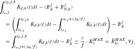
It can be also seen from Theorem 2, Fig. 4, and equation (A.1) that the condition for preventing decoder buffer overflow is
 $$\eqalign{&\int_{t{_e,j}}^{t{_d,j,k}} R_{d,k} (t)dt-(B_E^j +B_{N,k}^j)\cr &\quad = \left(\int_{t{_{e,j}}}^{t_{d,j,k}} R_{d,k} (t)dt - \int_{t{_{e,j}}}^{t_{e,j} +(\Delta_k /f)} R_{d,k} (t) dt \right) - B_E^j \cr &\quad = \int_{t{_e,j}+(\Delta_k / f)}^{t_d,j,k} R_{d,k} (t)dt-B_E^j \le {c \over f}\cdot R_e^{MAX} = \bar{B}_D^{MAX}, \forall j.}$$
This completes the proof.
Proof of Corollary 2
If the network for the kth video path between the output of the encoder buffer and the input of the decoder buffer has a fixed delay Δk/f with a jitter δk/f at t ò T for all j, then the aggregate network buffer fullness ![]() $B_{N,k}^{j} $ will be bounded by
$B_{N,k}^{j} $ will be bounded by
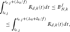 $$\eqalign{&\int_{t_{e,j}}^{t_{e,j} +(\Delta_k /f)} R_{d,k} (t)dt\le B_{N,k}^j \cr &\quad \le \int_{t_{e,j}}^{t_{e,j} +(\Delta_k +\delta_k /f)} R_{d,k} (t)dt,}$$
i.e., the aggregate network buffer B N, k contains at least all video data ready for entering the decoder buffer in the next Δk/f time interval, but no more than the video data ready for entering the decoder buffer in the next ![]() $\Delta_{k} +\delta_{k} /f$ time interval.
$\Delta_{k} +\delta_{k} /f$ time interval.
If the following inequality holds,
 $$\eqalign{& P_E^j + B_E^j + B_{N,k}^j \le P_E^j + B_E^j + \int_{t_{e,j}}^{t_{e,j} +(\Delta_k + \delta_k )/f} \cr & \quad R_{d,k} (t)dt \le \int_{t_{e,j}}^{t_{d,j,k}} R_{d,k} (t)dt, \forall j,}$$
i.e.
 $$P_E^j +B_E^j \le \int_{t_{e,j} + (\Delta_k + \delta_k)/f}^{t_{d,j,k}} R_{d,k} (t)dt, \forall j$$
it can be seen from Theorem 1 and equation (A.2) that this is a sufficient condition for preventing decoder buffer underflow.
It can be also seen from Fig. 5 that
Therefore, it follows directly from Theorem 2, equations (15) and (A.2) that a sufficient condition for preventing decoder buffer overflow is
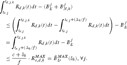 $$\eqalign{&\int_{t_{e,j}}^{t_{d,j,k}} R_{d,k} (t)dt - (B_E^j +B_{N,k}^j) \cr &\quad \le \left(\int_{t_{e,j}}^{t_{d,j,k}} R_{d,k} (t)dt - \int_{t_{e,j}}^{t_{e,j} +(\Delta_k /f)} R_{d,k} (t)dt \right) - B_E^j \cr &\quad = \int_{t_{e,j} + (\Delta_k /f)}^{t_{d,j,k}} R_{d,k} \lpar t \rpar dt - B_E^j \cr &\quad \le {c + \delta_k \over f} \cdot R_{e,d,k}^{MAX} = \bar{B}_D^{MAX} (\delta_k), \forall j.}$$
This completes the proof.
Proof of Corollary 3
From equation (A.2), we have
 $$B_{N,k}^j \le \int_{t_{e,j}}^{t_{e,j} +(\Delta_k +\delta_k /f)} R_{d,k} (t)dt.$$
If the video data transmitted from the input of the aggregate network buffer B N, k to the output of the dejitter buffer B d, k has a fixed delay ![]() $\Delta_{k} +\delta_{k} /f$ at t ò T for all j, then the aggregated network buffer B N, k and the dejitter buffer B d, k always contains all video data ready for entering the decoder buffer in the next
$\Delta_{k} +\delta_{k} /f$ at t ò T for all j, then the aggregated network buffer B N, k and the dejitter buffer B d, k always contains all video data ready for entering the decoder buffer in the next ![]() $\Delta_{k} +\delta_{k} /f$ time interval. Thus,
$\Delta_{k} +\delta_{k} /f$ time interval. Thus,
 $$B_{N,k}^j +B_{d,k}^j =\int_{t_{e,j}}^{t_{e,j} +(\Delta_k +\delta_k /f)} R_{d,k} (t)dt,\forall j.$$
Similar to Theorem 1, for the system given in Fig. 6, the condition for preventing decoder buffer underflow is
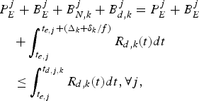 $$\eqalign{&P_E^j + B_E^j + B_{N,k}^j + B_{d,k}^j = P_E^j +B_E^j \cr &\quad + \int_{t_{e,j}}^{t_{e,j} + (\Delta_k + \delta_k /f)} R_{d,k} \lpar t \rpar dt \cr &\quad \le \int_{t_{e,j}}^{t_{d,j,k}} R_{d,k} (t)dt, \forall j,}$$
i.e.,
 $$P_E^j +B_E^j \le \int_{t_{e,j} +(\Delta_k +\delta_k /f)}^{t_{d,j,k}} R_{d,k} (t)dt, \forall j.$$
Also similar to Theorem 2, for the system given in Fig. 6, the condition for preventing decoder buffer overflow is
 $$\int_{t_{e,j}}^{t_{d,j,k}} R_{d,k} (t)dt-(B_E^j +B_{N,k}^j +B_{d,k}^j)\le \bar{B}_D^{MAX}$$
It can be also seen from equation (A.3) and the fact ![]() $t_{d,j,k} -(\Delta_{k} +\delta_{k} /f)-t_{e,j} =c/f$ that
$t_{d,j,k} -(\Delta_{k} +\delta_{k} /f)-t_{e,j} =c/f$ that
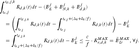 $$\eqalign{&\int_{t_e,j}^{t_d,j,k} R_{d,k} (t)dt-(B_E^j +B_{N,k}^j +B_{d,k}^j)\cr &\quad = \left(\int_{t_{e,j}}^{t_{d,j,k}} R_{d,k} (t)dt- \int_{t_{e,j}}^{t_{e,j} +(\Delta_k +\delta_k /f)} R_{d,k} (t)dt \right)-B_E^j \cr &\quad = \int_{t_{e,j}+(\Delta_k + \delta_k / f)}^{t_{d,j,k}} R_{d,k} (t)dt-B_E^j \le {c \over f}\cdot R_{e,d,k}^{MAX} =\bar{B}_D^{MAX}, \forall j.}$$
This completes the proof.
Sherman (Xuemin) Chen (aka Xuemin Chen) is the Vice President of Technology at Broadband and Connectivity Group (BCG) of Broadcom Corporation, responsible for the development and integration of new technologies into BCG System-on-Chips (SoCs), and driving the broadband technology roadmap to enable broadband media services to and throughout the home. Mr. Chen has a Ph.D. degree in Electrical Engineering from the University of Southern California. He is an IEEE fellow and a Broadcom Fellow, and an inventor of more than 280 issued US patents and 400 published patent applications worldwide in digital communications architecture, system, and signal processing. He has published over 80 research articles, reports, and book chapters, and three graduate-level textbooks on digital communications, entitled Error-Control Coding for Data Network, Transporting Compressed Digital Video, and Digital Video Transcoding for Transmission and Storage.
Gordon Yong Li held a B.Eng. degree from Chongqing University, China, and M.A.Sc. and Ph.D. degrees from the University of Toronto, Canada. He is currently a Technical Director with Broadband Technology Group, Broadcom Corporation. His professional interests cover research and{} development of broadband and wireless products and standards. He is an inventor of more than 60 issued or pending U.S. patents, and published more than a dozen academic papers in international conferences and journals.
