


1 Introduction
Laser technology finds extensive applications across various domains, including material processing[ Reference Chryssolouris, Anifantis and Karagiannis 1 , Reference Wang, Fang, An, Wu, Qi, Cai and Guo 2 ], remote sensing[ Reference Lux, Fritsche and Eichler 3 ] and medicine[ Reference Heeman, Steenbergen, van Dam and Boerma 4 , Reference Shirazi, Gharehkhani, Mehrali, Yarmand, Metselaar, Kadri and Osman 5 ]. These diverse fields impose stringent requirements on laser systems, such as power output, beam quality and specific wavelengths, which have significantly propelled the development of advanced laser technologies. For high-power lasers, overheating within the gain medium poses a fundamental limitation on achieving higher power levels. To address this challenge, several approaches have been adopted, encompassing the development of disk lasers, slab lasers and fiber lasers[ Reference Zuo and Lin 6 ], the implementation of enhanced temperature control measures[ Reference Fan, Member, Ripin, Aggarwal, Ochoa, Chann, Tilleman and Spitzberg 7 ] and the utilization of gain media with superior thermal properties. These advancements have effectively augmented the output power capabilities of lasers.
In terms of selecting an appropriate gain medium, diamond Raman lasers (DRLs) stand out due to their unique characteristics. DRLs employ diamond as the gain medium and operate based on stimulated Raman scattering (SRS). Compared to other gain crystals, diamond exhibits distinct advantages, including a significant Raman frequency shift (1332.3 cm–1), high Raman gain coefficient (10 cm/GW@1 μm), narrow gain linewidth (1.5 cm–1) and broad transmission window from 230 nm to 100 μm[ Reference Mildren 8 ]. Of particular significance is diamond’s exceptional thermal conductivity, reaching 2000 W/(m·K), surpassing other crystal materials. In addition, its moderate thermo-optic coefficient (20 × 10–6 K−1 ) and extremely low thermal expansion coefficient (1.1 × 10⁻⁶ m/K) considerably mitigate the thermal lens effect observed in high-power DRLs[ Reference Williams, Nold, Strecker, Kitzler, McKay, Schreiber and Mildren 9 , Reference Bai, Zhang, Wang, Gao, Zhang, Yang, Wang, Lu and Mildren 10 ]. These attributes enable DRLs to generate continuous-wave (CW) output powers exceeding hundreds of watts, markedly surpassing the performance limitations of conventional Raman media such as potassium gadolinium tungstate (KGW) and neodymium-doped yttrium orthovanadate (Nd:YVO4) crystals, which typically achieve outputs limited to tens of watts[ Reference Chen, Pan, Liu, Cheng, Tsou and Liang 11 , Reference Sheng, Geng, Liu, Fu, Shi and Yao 12 ]. Consequently, DRLs have garnered substantial attention from researchers in the field.
The maturation of chemical vapor deposition (CVD) diamond technology accelerated the development of DRLs. In 2012, Kitzler et al. [ Reference Kitzler, McKay and Mildren 13 ] pioneered an external-cavity DRL configuration, achieving 10.1 W CW output. Williams et al.[ Reference Williams, Nold, Strecker, Kitzler, McKay, Schreiber and Mildren 9 ] subsequently demonstrated a landmark 1240 nm Stokes CW output of 154 W in 2015, which remains the highest reported power for fundamental Stokes CW DRLs to date. Subsequent power scaling progress includes the demonstration of 1.2 kW quasi-CW Stokes output by Antipov et al. [ Reference Antipov, Sabella, Williams, Kitzler, Spence and Mildren 14 ] in 2019, and the report of 63 W CW second-Stokes emission at 1744 nm with more than 30% conversion efficiency by Heinzig et al. [ Reference Heinzig, Palma-Vega, Yildiz, Walbaum, Schreiber and Tünnermann 15 ] in 2021, representing the highest power achieved for cascaded DRLs. Most recently, Sharp et al. [ Reference Sharp, Jasbeer, Pahlavani, Spence, Kitzler, Yang and Mildren 16 ] attained 60 W at 607 nm via intracavity frequency doubling in lithium triborate (LBO) in 2024.
Despite the landmark achievement of a 154 W CW DRL in 2015, subsequent power scaling endeavors have yielded no substantial progress in high-power CW output. This stagnation deviates from theoretical projections of DRL capabilities for high-power applications. Three fundamental limitations underlie this plateau: (i) scarcity of high-power pump sources with sub-45 GHz spectral linewidths; (ii) thermal effects in the cavity destabilizing cavity dynamics and impeding power enhancement; and (iii) intracavity power density exceeding optical coating damage thresholds on resonator components. These constraints – encompassing insufficient power budgets, unresolved thermal management and coating performance – collectively constitute major challenges to power scaling in DRLs.
This study demonstrates a high-power CW DRL operating at 1240 nm. To address pump power requirements, polarization beam combining of dual-fiber lasers was implemented. A single-pass quasi-Z-shaped resonator was designed to optimize intracavity power density and output efficiency to mitigate back-reflection through integrated optical isolators in the pump path. All optical surfaces were angled to minimize parasitic reflections. Furthermore, active thermal management via water-cooled mounts and thermoelectric modules stabilized cavity optics with high damage threshold coatings, suppressing thermal aberrations and enhancing component survivability. These methods yielded a record output power of 213.4 W with 64.1% slope efficiency, representing the highest reported CW DRL performance to date.
2 Experimental setup
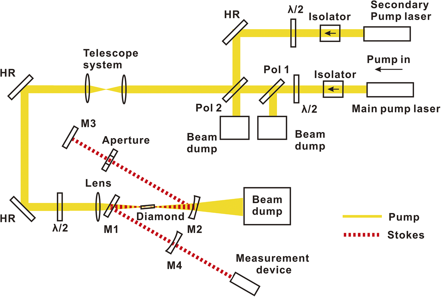
The experimental setup is depicted in Figure 1, where a pump source comprising two fiber lasers with polarization beam combining was employed to meet the pump power requirements. The primary laser exhibited an output power of up to 350 W with M 2 = 1.12 and 20 GHz linewidth, while the secondary laser had an identical M 2 factor and linewidth but 200 W output power. Notably, both lasers utilize the same seed laser, ensuring identical spectral outputs. Two isolators were positioned after the laser output ports to prevent back-reflection light. To maintain stable thermal effects within the isolators, the pump lasers operated at their maximum power levels, and half-wave plates along with quartz polarizers served as attenuators. The primary pump laser emitted light with vertical polarization, whereas the secondary pump laser produced horizontally polarized light. These beams were combined into a single beam using polarizer 2 (Pol 2). After passing through a telescope system, the merged pump beam was directed towards a half-wave plate for polarization adjustment and then passed through a plano-convex lens with 200 mm focal length to achieve mode-matching between the pump and Stokes beams within the diamond medium. The calculated beam waist radii for the pump and Stokes beams inside the diamond were 26 and 50 μm, respectively. Under high-power operational regimes, residual reflectivity as low as 0.5% on cavity mirror surfaces can generate watt-scale back-reflected power. Given the optical isolator’s limited 28 dB extinction ratio, this component proves insufficient to fully mitigate back-reflection effects. Therefore, all optics in the pump beam path must be tilted to eliminate back-reflection.

Figure 1 The experimental setup. HR, high-reflection mirror; λ/2, half-wave plate; Pol, polarizer; M1–M4, cavity mirrors.
The cavity comprised four mirrors labeled M1–M4, with configurations detailed in Table 1. All mirrors exhibited high transmissivity for the pump wavelength to prevent potential back-reflection and high transmissivity at 1485 nm to suppress second-Stokes oscillation. Mirror M1 functioned as an input coupler (IC), while M4 served as an output coupler (OC). The 3.2% output coupling ratio was determined based on the external-cavity Raman laser model[
Reference Kitzler, McKay, Spence and Mildren
17
]. Although mirror distribution formed a Z-shaped cavity, allowing for tilting M1 and M2 to prevent pump back-reflection, the planar IC mirror created V-shaped caustics. This configuration, classified as quasi-Z-shaped, produced larger beam sizes at the OC than a true Z-cavity, thereby reducing power density. To mitigate thermal effects on the cavity mirrors, they were mounted on water-cooled mirror mounts. The Raman gain medium was a single-crystal diamond measuring 2 mm × 2 mm × 7 mm (Type IIa, Element Six Ltd.) with anti-reflective coatings at 1064 and 1240 nm (Dientech Ltd.), cut for propagation along the $\left[1\overline{1}0\right]$
direction. The diamond was secured onto a copper holder, and its temperature was maintained at 30°C using a thermoelectric cooler (TEC) module. To suppress parasitic stimulated Brillouin scattering (SBS) oscillating within the DRL resonator, cavity length tuning was employed to confine SBS oscillation to higher-order transverse modes. A variable aperture was subsequently positioned between mirrors M2 and M3 to suppress higher-order transverse modes[
Reference Li, Yang, Sun, Jiang, Mildren, Kitzler, Spence and Feng
18
,
Reference Li, Spence, Sun, Yang and Feng
19
].
$\left[1\overline{1}0\right]$
direction. The diamond was secured onto a copper holder, and its temperature was maintained at 30°C using a thermoelectric cooler (TEC) module. To suppress parasitic stimulated Brillouin scattering (SBS) oscillating within the DRL resonator, cavity length tuning was employed to confine SBS oscillation to higher-order transverse modes. A variable aperture was subsequently positioned between mirrors M2 and M3 to suppress higher-order transverse modes[
Reference Li, Yang, Sun, Jiang, Mildren, Kitzler, Spence and Feng
18
,
Reference Li, Spence, Sun, Yang and Feng
19
].
Table 1 Configuration of the cavity mirrors a .
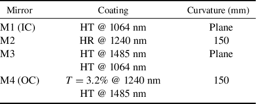
a HT, high transmission; HR, high reflection.
3 Results and discussion
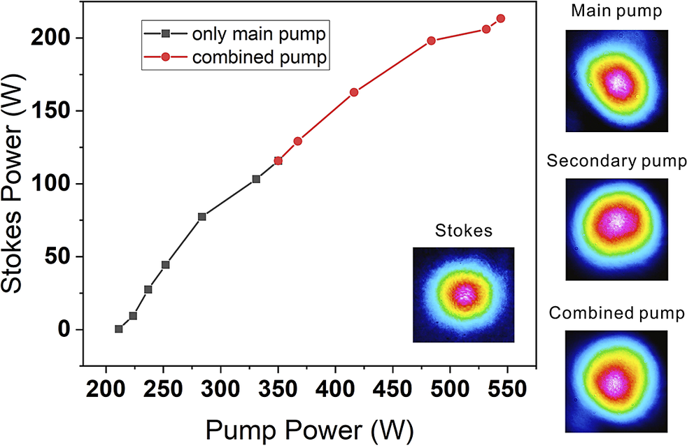
Figure 2 presents Stokes output power as a function of pump power, characterized using calibrated power meters (F600-CB-55/F250-CB-40, Caihuang Thermoelectricity Co., Ltd.). The Stokes threshold occurred at 211 W, achieving a maximum output of 213.4 W at 544 W pump power, corresponding to 64.1% slope efficiency and 39.2% optical-to-Stokes conversion efficiency. Below 350 W (black curve), only the vertically polarized primary pump was used. Beyond this power (red curve), combined pumping was initiated with the secondary pump maintaining orthogonal horizontal polarization. In contrast to the maximum 5-s operational duration reported in Ref. [Reference Williams, Nold, Strecker, Kitzler, McKay, Schreiber and Mildren9], the DRL demonstrated sustained operation exceeding 20 s at peak input power, yielding an average Stokes output power of approximately 200 W. Besides, during cavity optimization procedures, the system maintained operation above 180 W for over 1 min, confirming the thermal and optical stability of the configuration under high-power operating conditions. The similar slope efficiency observed under both regimes arises from polarization-matched gain characteristics[ Reference Kitzler, Spence and Mildren 20 ]. Note that the slope efficiency under combined pumping conditions shows a marginal reduction relative to single-pump operation, which may be attributed to the following: (i) spatial mode mismatch between the two pump components; and (ii) increasingly pronounced thermal effects. The inset depicts Stokes beam profiles acquired via a beam profiler (WinCamD-LCM, DataRay Inc.), consistently exhibiting the fundamental TEM00 mode regardless of pump-combining status. Adjacently, pump beam profiles exhibit wavefront distortions attributed to thermal aberrations from isolator components. To prevent potential damage to resonant cavity components, extended duration testing was deliberately limited. Nevertheless, the DRL still incurred damage upon reducing the pump power from its maximum to 10 W. We attributed this failure to the rapid decrease in pump power, which likely induced thermal contraction effects, leading to the detachment and failure of the diamond coating.

Figure 2 Output Stokes power as a function of pump power; the inset shows the Stokes beam profile, and also included are the beam profile for the main pump, secondary pump and combined pump.
The influence of pump beam combining on Stokes polarization was investigated via polarization-resolved analysis using a half-wave plate and a polarizing beam splitter (PBS). Figure 3 presents a quantitative analysis of Stokes power distribution, where the black and red curves correspond to the vertical and horizontal polarization components, respectively, as measured through the PBS. Analysis of the Stokes power modulation versus waveplate rotation angle demonstrates that Stokes polarization maintains near-horizontal alignment, exhibiting only a minor deviation of approximately 4 deg. This behavior is consistently observed under both pumping configurations: single vertically polarized pump excitation (Figure 3(a)) and orthogonally polarized dual-pump operation (Figure 3(b)). This polarization invariance confirms that secondary pumps amplify the existing Stokes field rather than seeding new oscillations.
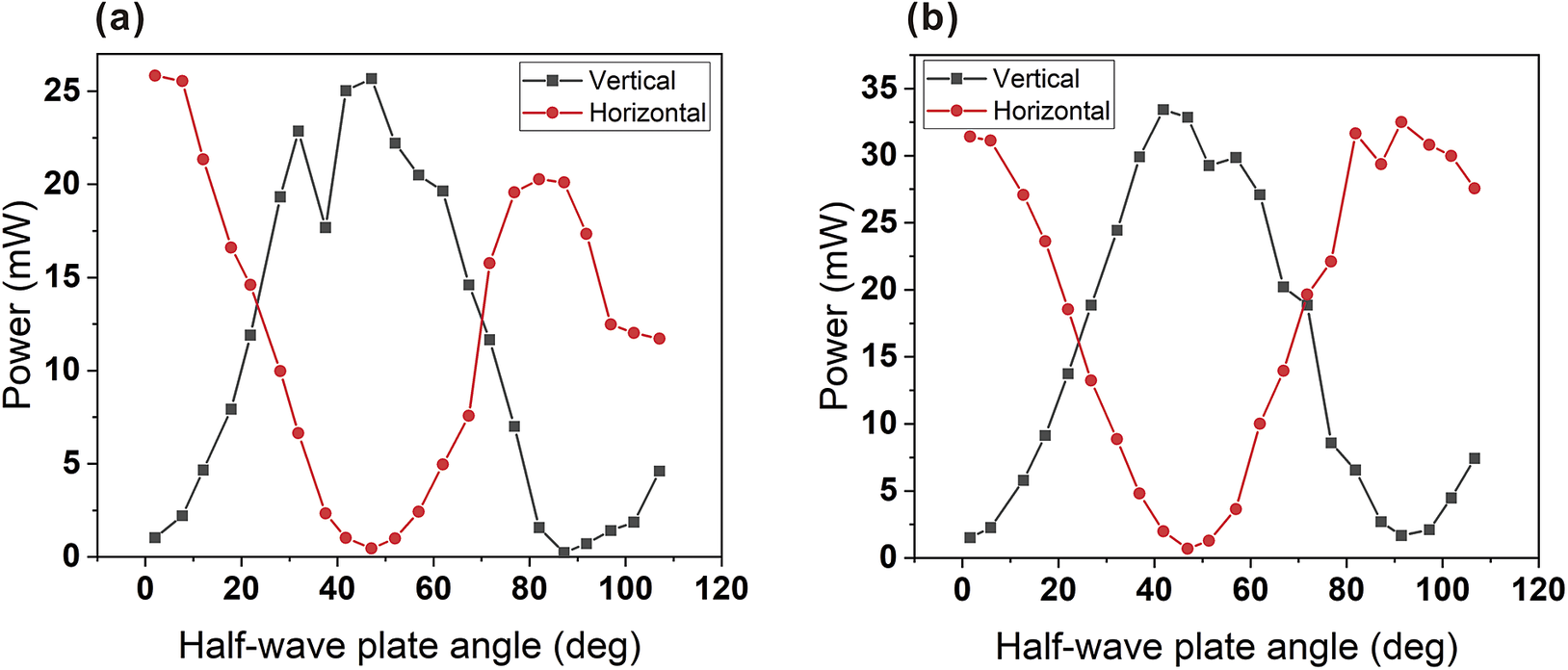
Figure 3 Power as a function of the half-wave plate angle of (a) the main pump alone with vertical polarization and (b) the combined pump with vertical and horizontal polarizations. Note that when the angle of the half-wave plate is zero, its fast axis aligns horizontally.
The influence of pump polarization on Stokes output power was characterized via half-wave plate rotation and subsequent Stokes power measurement. Experimental data demonstrated maximal Stokes output when pump polarization was aligned with either vertical or horizontal orientations. Based on the theoretical framework in Ref. [Reference Kitzler, Spence and Mildren20] relating to pump polarization, Stokes polarization and Raman gain, we computationally reconstructed the normalized gain coefficient $\chi ({\theta}_\mathrm{P},{\theta}_\mathrm{S})$
to quantify gain dynamics in orthogonally polarized pump-combining architectures. Figure 4 presents these polarization-parameterized gain distributions for the primary pump alone (Figure 4(a)), orthogonally polarized secondary pump (Figure 4(b)) and coherently combined pump (Figure 4(c)). Although the Stokes field exhibits the highest gain (1.33χ) when the pump polarization aligns with the [111] direction of the diamond, the orthogonally polarized secondary pump exhibits substantially reduced gain (0.35χ), resulting in a suboptimal combined gain of 1.68χ. In contrast, vertical/horizontal polarization configurations enable both pump components to achieve identical χ coefficients, attaining the theoretical maximum combined gain of 2χ for dual orthogonally polarized pumps. Note that the complementary gain profiles in Figures 4(a) and 4(b) produce pump-polarization-insensitive combined gain in Figure 4(c). This simplified model, however, neglects diamond birefringence effects on Stokes polarization evolution and assumes equitable pump intensity weighting. Consequently, a discrepancy emerges between theoretical predictions and experimental observations: while Figure 4(c) indicates maximum Stokes gain at horizontal polarization, empirical measurements exhibit a 4 deg polarization deviation. Further investigation into polarization-dependent gain dynamics in diamond under orthogonal polarization states is therefore imperative.
$\chi ({\theta}_\mathrm{P},{\theta}_\mathrm{S})$
to quantify gain dynamics in orthogonally polarized pump-combining architectures. Figure 4 presents these polarization-parameterized gain distributions for the primary pump alone (Figure 4(a)), orthogonally polarized secondary pump (Figure 4(b)) and coherently combined pump (Figure 4(c)). Although the Stokes field exhibits the highest gain (1.33χ) when the pump polarization aligns with the [111] direction of the diamond, the orthogonally polarized secondary pump exhibits substantially reduced gain (0.35χ), resulting in a suboptimal combined gain of 1.68χ. In contrast, vertical/horizontal polarization configurations enable both pump components to achieve identical χ coefficients, attaining the theoretical maximum combined gain of 2χ for dual orthogonally polarized pumps. Note that the complementary gain profiles in Figures 4(a) and 4(b) produce pump-polarization-insensitive combined gain in Figure 4(c). This simplified model, however, neglects diamond birefringence effects on Stokes polarization evolution and assumes equitable pump intensity weighting. Consequently, a discrepancy emerges between theoretical predictions and experimental observations: while Figure 4(c) indicates maximum Stokes gain at horizontal polarization, empirical measurements exhibit a 4 deg polarization deviation. Further investigation into polarization-dependent gain dynamics in diamond under orthogonal polarization states is therefore imperative.
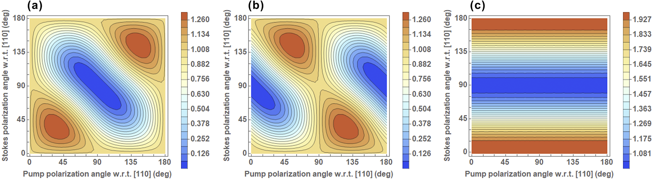
Figure 4 The normalized Raman gain coefficient χ as a function of pump and Stokes polarization angles for the (a) primary pump, (b) orthogonally polarized secondary pump and (c) combined pump configuration.
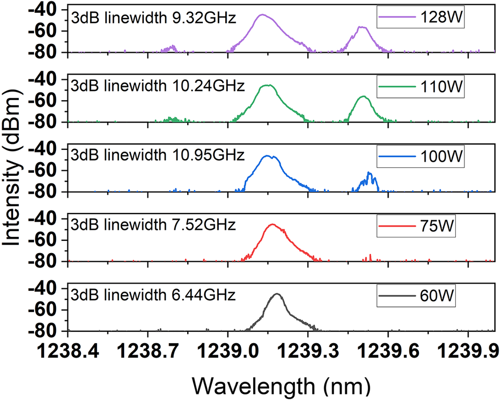
The mitigation of SBS is critical for maximizing Stokes field performance, as SBS constitutes a dominant loss mechanism that destabilizes SRS gain. Implementation of high-order transverse mode excitation in the SBS field via cavity length optimization, coupled with intracavity spatial filtering via an aperture to suppress high-order SBS oscillations[ Reference Li, Spence, Sun, Yang and Feng 19 ], enabled complete SBS suppression until Stokes power exceeded 75 W. As the spectral data in Figure 5 demonstrate (with the legend indicating Stokes power levels), significant SBS intensity emerged at 100 W Stokes power, followed by anti-Stokes line emergence at 110 W. Following the observed coating damage on the diamond, the DRL system was reconfigured utilizing an undamaged region of the diamond cross-section. However, this alternative configuration exhibited suboptimal Raman gain and birefringence characteristics, consequently limiting the maximum attainable Stokes power to 128 W, where unambiguous anti-Stokes signatures were observed. Extrapolation suggests SBS cascade amplification will intensify with further power scaling, inducing progressive Stokes power instability. While spatial filtering provides partial suppression of SBS, its efficacy diminishes at high Stokes power regimes. Achieving comprehensive SBS suppression necessitates either stringent enhancements to spatial filtering methodologies (e.g., more apertures) or exploitation of second-order nonlinear processes[ Reference Li, Yang, Sun, Jiang, Mildren, Kitzler, Spence and Feng 18 , Reference Yang, Kitzler, Spence, Williams, Bai, Sarang, Zhang, Feng and Mildren 21 – Reference Liu, Zhu, Sun, Mildren, Bai, Zhang, Chen, Chen, Li, Yang and Feng 23 ]. These approaches enable robust Stokes power stabilization critical for high-power scaling applications. In addition, the 3 dB linewidth of SRS was expanded from 6.44 GHz at 60 W to 7.52 GHz at the SBS threshold of 75 W, and then to approximately 10 GHz when SRS power exceeded 100 W. This linewidth broadening may correlate with the increase in SRS power and the intensity of first-order SBS. Further investigation is required to elucidate the underlying mechanism to determine the role of SBS in the linewidth of SRS.

Figure 5 Spectral evolution of Stokes emission across incrementally scaled output power levels, with corresponding power values annotated in the legend.
This configuration employed a quasi-Z-shaped cavity with single-pass pumping to eliminate back-reflections, contrasting with the prior CW DRL output record holder[ Reference Williams, Nold, Strecker, Kitzler, McKay, Schreiber and Mildren 9 ]. Despite introducing additional mirror-induced losses, the architecture maintained operational integrity at kilowatt-level pump powers. Thermal management innovations included (i) water-cooled mirror mounts mitigating thermo-optic instabilities[ Reference Williams, Nold, Strecker, Kitzler, McKay, Schreiber and Mildren 9 ] and (ii) TEC regulation constraining diamond temperatures below 40°C at maximum output. Polarization beam combining overcame individual laser power limitations and fabrication constraints for high-power optical isolators. By distributing pump intensity across spatially dispersed channels, this approach reduced isolator power density, enabling back-reflection suppression without requiring large diamond angular displacement for gain optimization. Furthermore, this methodology enables the implementation of narrow-linewidth, randomly polarized fiber lasers as pump sources for DRLs. These pumps deliver kilowatt-class output while exhibiting enhanced resilience to optical feedback. Notably, despite diamond’s inherent polarization-dependent Raman gain, a polarization-insensitive regime emerges when the Stokes field maintains horizontal polarization. Under this condition, equivalent gain coefficients are observed for both horizontally and vertically polarized pumping. This phenomenon substantially mitigates output power fluctuations induced by pump polarization instability, thereby enhancing system robustness in high-power operation. To the best of our knowledge, this work represents the first implementation of polarization beam combining in DRLs to address insufficient individual pump power for enhanced Stokes output. Future investigations should establish polarization optimization criteria for arbitrary pump power ratios in combined-beam architectures.
4 Conclusion
In conclusion, a CW DRL operating at 1240 nm was demonstrated by employing pump beam combination to enhance the power of the pump source and utilizing a quasi-Z-shaped cavity design to mitigate back-reflection. The Stokes output power reached 213.4 W, surpassing the previous 154 W record for CW DRL that had stood for 10 years. Furthermore, the polarization characteristics of the Stokes field were examined to validate the amplification role played by the secondary pump beam. Moreover, in addition to back-reflection prevention and thermal management, effective suppression of intracavity SBS constituted a fundamental enabling factor for power scaling.
Acknowledgements
This work was supported by the National Key Research and Development Program of China (Grant Nos. 2024YFB3613800 and 2024YFE0206000) and the National Natural Science Foundation of China (Grant No. 12473080).


 Open access