


1 Introduction
The rapid development of ultrafast and ultra-intense laser systems opens up a new path to extreme conditions in the laboratory, such as ultrafast time scales, ultra-intense electromagnetic fields and ultra-high energy densities, which are of significant interest to research into ultrafast molecular dynamics[
Reference Zewail1], laboratory astrophysics[
Reference Remington, Drake and Ryutov2,
Reference Bulanov, Esirkepov, Habs, Pegoraro and Tajima3], laser-driven nuclear physics[
Reference Habs, Tajima, Schreiber, Barty, Fujiwara and Thirolf4,
Reference Zylstra, Hurricane, Callahan, Kritcher, Ralph, Robey, Ross, Young, Baker, Casey, Döppner, Divol, Hohenberger, Le Pape, Pak, Patel, Tommasini, Ali, Amendt, Atherton, Bachmann, Bailey, Benedetti, Hopkins, Betti, Bhandarkar, Biener, Bionta, Birge, Bond, Bradley, Braun, Briggs, Bruhn, Celliers, Chang, Chapman, Chen, Choate, Christopherson, Clark, Crippen, Dewald, Dittrich, Edwards, Farmer, Field, Fittinghoff, Frenje, Gaffney, Johnson, Glenzer, Grim, Haan, Hahn, Hall, Hammel, Harte, Hartouni, Heebner, Hernandez, Herrmann, Herrmann, Hinkel, Ho, Holder, Hsing, Huang, Humbird, Izumi, Jarrott, Jeet, Jones, Kerbel, Kerr, Khan, Kilkenny, Kim, Kleinrath, Kleinrath, Kong, Koning, Kroll, Kruse, Kustowski, Landen, Langer, Larson, Lemos, Lindl, Ma, MacDonald, MacGowan, Mackinnon, MacLaren, MacPhee, Marinak, Mariscal, Marley, Masse, Meaney, Meezan, Michel, Millot, Milovich, Moody, Moore, Morton, Murphy, Newman, Di Nicola, Nikroo, Nora, Patel, Pelz, Peterson, Ping, Pollock, Ratledge, Rice, Rinderknecht, Rosen, Rubery, Salmonson, Sater, Schiaffino, Schlossberg, Schneider, Schroeder, Scott, Sepke, Sequoia, Sherlock, Shin, Smalyuk, Spears, Springer, Stadermann, Stoupin, Strozzi, Suter, Thomas, Town, Tubman, Trosseille, Volegov, Weber, Widmann, Wild, Wilde, Van Wonterghem, Woods, Woodworth, Yamaguchi, Yang and Zimmerman5] and laser–plasma accelerators[
Reference Tajima and Dawson6–
Reference Zhu, Chen, Weng, Yu, Wang, He, Sheng, McKenna, Jaroszynski and Zhang14], as well as strong-field quantum electrodynamics (SF QED)[
Reference Cole, Behm, Gerstmayr, Blackburn, Wood, Baird, Duff, Harvey, Ilderton, Joglekar, Krushelnick, Kuschel, Marklund, McKenna, Murphy, Poder, Ridgers, Samarin, Sarri, Symes, Thomas, Warwick, Zepf, Najmudin and Mangles15,
Reference Poder, Tamburini, Sarri, Di Piazza, Kuschel, Baird, Behm, Bohlen, Cole, Corvan, Duff, Gerstmayr, Keitel, Krushelnick, Mangles, McKenna, Murphy, Najmudin, Ridgers, Samarin, Symes, Thomas, Warwick and Zepf16]. Tightly focused high-peak-power laser pulses with intensity exceeding ${10}^{18}\ \mathrm{W}/{\mathrm{cm}}^2$
also open up new horizons in the relativistic optics regime. For many applications, the preferred extreme intensity greater than
${10}^{18}\ \mathrm{W}/{\mathrm{cm}}^2$
also open up new horizons in the relativistic optics regime. For many applications, the preferred extreme intensity greater than ${10}^{22}\ \mathrm{W}/{\mathrm{cm}}^2$
[
Reference Bahk, Rousseau, Planchon, Chvykov, Kalintchenko, Maksimchuk, Mourou and Yanovsky17,
Reference Yoon, Jeon, Shin, Lee, Lee, Choi, Kim, Sung and Nam18] or even
${10}^{22}\ \mathrm{W}/{\mathrm{cm}}^2$
[
Reference Bahk, Rousseau, Planchon, Chvykov, Kalintchenko, Maksimchuk, Mourou and Yanovsky17,
Reference Yoon, Jeon, Shin, Lee, Lee, Choi, Kim, Sung and Nam18] or even ${10}^{23}\ \mathrm{W}/{\mathrm{cm}}^2$
[
Reference Yoon, Kim, Choi, Sung, Lee, Lee and Nam19] is only obtainable within a micrometer-sized focal spot. Therefore, taking full advantage of these lasers’ extreme intensity at focus requires precise control of the laser beam pointing.
${10}^{23}\ \mathrm{W}/{\mathrm{cm}}^2$
[
Reference Yoon, Kim, Choi, Sung, Lee, Lee and Nam19] is only obtainable within a micrometer-sized focal spot. Therefore, taking full advantage of these lasers’ extreme intensity at focus requires precise control of the laser beam pointing.
The construction of the Zettawatt-Equivalent Ultrashort pulse laser System (ZEUS) at the University of Michigan will enable flagship experiments designed to collide a high-energy electron beam from a laser wakefield accelerator (LWFA) with a focused ultrashort laser pulse[ Reference Nees, Maksimchuk, Kalinchenko, Hou, Ma, Campbell, McKelvey, Willingale, Jovanovic, Kuranz, Thomas and Krushelnick20, Reference Willingale, Maksimchuk, Nees, Bayer, Burger, Campbell, Hou, Jovanovic, Kalinchenko, Kuranz, Ma, McKelvey, Thomas, Weinberg, Zhang and Krushelnick21]. Such an experiment would enable the study of the new physics in SF QED via two basic processes, that is, multi-photon Compton scattering and multi-photon Breit–Wheeler pair-production, in the collision of high-energy electrons and high-intensity laser pulses[ Reference Zhang, Bulanov, Seipt, Arefiev and Thomas22– Reference Fedotov, Ilderton, Karbstein, King, Seipt, Taya and Torgrimsson24]. The designed diameter of the electron beam at the interaction point is less than 100 μm. Consequently, the positional deviation of the focused laser pulse must be within this range so that the interaction between them can be realized. This requires both the wakefield-driver laser and the colliding laser to have minimal beam-pointing instabilities (less than a few μrad). Besides the colliding experiment, the production of relativistic electron beams with narrow energy spread through the LWFA would also benefit from a pointing-stabilized high-power laser[ Reference Faure, Rechatin, Norlin, Lifschitz, Glinec and Malka25– Reference Ma, Seipt, Dann, Streeter, Palmer, Willingale and Thomas27], in addition to enabling a wide variety of temporally resolved pump–probe experiments.
2 Theoretical background
To control laser beam pointing, a fast tip/tilt mirror is often employed rather than a deformable mirror. Due to the relatively low laser-induced damage thresholds of optical coatings (a few $\mathrm{J}/{\mathrm{cm}}^2$
), large-diameter beams and, consequently, mirrors with large apertures, are required in high-power laser systems. To preserve the surface flatness, the minimum thickness of a large-aperture optic scales with its aperture (
$\mathrm{J}/{\mathrm{cm}}^2$
), large-diameter beams and, consequently, mirrors with large apertures, are required in high-power laser systems. To preserve the surface flatness, the minimum thickness of a large-aperture optic scales with its aperture ( $d$
). As a result, the mass of such optics scales as the cube of the optical aperture.
$d$
). As a result, the mass of such optics scales as the cube of the optical aperture.
The natural frequency of a mechanical system on its ith degree of freedom can be depicted as follows[ Reference Den Hartog28]:
 $$\begin{align}{f}_i=\frac{1}{2\pi}\sqrt{\frac{K_i}{J_i}},\end{align}$$
where ${K}_i$
and
${K}_i$
and ${J}_i$
denote the stiffness and inertial mass on its ith degree of freedom. Equation (1) illustrates the bandwidth limitation of large-aperture, tip/tilt mirrors, as their natural frequencies are inversely proportional to their aperture (to the power of –3/2). Two approaches could be pursued to improve a tip/tilt mirror’s bandwidth: increasing the stiffness or decreasing the inertial mass. The first approach usually involves a comprehensive design, finite element analysis (FEA) and customization of rigid flexures[
Reference Nam, Gimm, Kang and Gweon29,
Reference Woody and Smith30]. The latter could be achieved using lightweight materials and complex structures such as honeycombs[
Reference Stein and Neufeld31].
${J}_i$
denote the stiffness and inertial mass on its ith degree of freedom. Equation (1) illustrates the bandwidth limitation of large-aperture, tip/tilt mirrors, as their natural frequencies are inversely proportional to their aperture (to the power of –3/2). Two approaches could be pursued to improve a tip/tilt mirror’s bandwidth: increasing the stiffness or decreasing the inertial mass. The first approach usually involves a comprehensive design, finite element analysis (FEA) and customization of rigid flexures[
Reference Nam, Gimm, Kang and Gweon29,
Reference Woody and Smith30]. The latter could be achieved using lightweight materials and complex structures such as honeycombs[
Reference Stein and Neufeld31].
The above-mentioned aperture-bandwidth dilemma for tip/tilt mirrors has been posing significant challenges for the high-power laser community as well as for applications of these lasers. In fact, most actively controlled tip/tilt mirrors or mechanisms reported in the literature[ Reference Kanai, Suda, Bohman, Kaku, Yamaguchi and Midorikawa32– Reference Berger, Barber, Isono, Jensen, Natal, Gonsalves and van Tilborg38] or that are commercially available[ 39] are limited to approximately 4 inches (1 inch = 2.54 cm) in diameter. Although large-aperture tip/tilt mirrors are widely used in astronomical telescopes[ Reference Stein and Neufeld31], their high cost, heavy weight and large footprint make them less attractive candidates for use in table-top high-power laser systems in academic or industrial laboratories.
3 Design considerations
The aim of this investigation is to develop a cost-effective, compact, large-aperture, fast tip/tilt mirror that would mainly utilize off-the-shelf components to enhance the pointing stability of a very high-power laser system. The positional stability of the collimated ZEUS laser beam is sufficient to avoid beam clipping; however, pointing stability improvements such as those demonstrated in this work can significantly enhance the viability of colliding experiments that depend on control of the focal spot location. Several considerations were carefully weighed during the design phase, including employing a low-profile design to accommodate the 12-inch beam’s height from upstream and maintaining the ability to detect the beam leakage through the mirrors. Mechanical simulations were conducted to enhance the stiffness-to-mass ratio of the mirror in the horizontal and vertical directions, thus increasing the mirror’s resonance frequency (Equation (1)).
In this work, we present a proof-of-principle study of actively controlling a 16-inch mirror assembly by sampling a continuous-wave (CW) laser diode output at 100 Hz, which effectively resembles the regenerative amplifier of the ZEUS laser operating at the same repetition rate. It has been demonstrated that the low-power, unamplified pulse train from the front-end of a laser system (100 Hz for the ZEUS laser) carries the same beam-pointing properties as the high-power, fully amplified pulses (1/60 Hz for the ZEUS laser) originated from the same front-end[
Reference Isono, van Tilborg, Barber, Natal, Berger, Tsai, Ostermayr, Gonsalves, Geddes and Esarey35]. As a result, actively controlling the beam pointing of the unamplified pulses within the 100-Hz pulse train leads to optimized pointing stability of the fully amplified beam (selected pulses from the same 100-Hz pulse train) at the focus. A simple proportional feedback control was implemented to serve this purpose. For industry-standard proportional–integral–derivative (PID) control algorithms, the correcting signal output $u(t)$
as a function of the error signal input
$u(t)$
as a function of the error signal input $e(t)$
can be expressed as
$e(t)$
can be expressed as $u(t)={K}_{\mathrm{P}}e(t)+{K}_{\mathrm{I}}\int e(t)\mathrm{d}t+{K}_{\mathrm{D}}\frac{\mathrm{d}e(t)}{\mathrm{d}t}$
, where
$u(t)={K}_{\mathrm{P}}e(t)+{K}_{\mathrm{I}}\int e(t)\mathrm{d}t+{K}_{\mathrm{D}}\frac{\mathrm{d}e(t)}{\mathrm{d}t}$
, where ${K}_{\mathrm{P}}$
,
${K}_{\mathrm{P}}$
, ${K}_{\mathrm{I}}$
and
${K}_{\mathrm{I}}$
and ${K}_{\mathrm{D}}$
are the proportional, integral and derivative coefficients, respectively. In this work, only the first proportional term is taken into account for simplicity and the baseline timing study; thus, the correcting signals driving the piezo-actuators
${K}_{\mathrm{D}}$
are the proportional, integral and derivative coefficients, respectively. In this work, only the first proportional term is taken into account for simplicity and the baseline timing study; thus, the correcting signals driving the piezo-actuators $u(t)={K}_{\mathrm{P}}e(t)$
. The error signal input
$u(t)={K}_{\mathrm{P}}e(t)$
. The error signal input $e(t)$
is generated by a position sensing detector, which monitors the position of the focal spot’s centroid.
$e(t)$
is generated by a position sensing detector, which monitors the position of the focal spot’s centroid.
4 Design overview
Actuating such a large optic is critical due to the requirement for independent control of the 12-inch laser beam pointing after the final amplifier for the colliding experiment discussed above. Therefore, we implemented a simple proportional feedback control and observed reductions of the standard deviation of beam-pointing fluctuations by 91% and 78% in the horizontal and vertical directions, respectively. Although the geometrical and mechanical properties of the fast tip/tilt mirror were tailored to meet the ZEUS laser’s requirement, other high-power laser facilities can easily adopt this study’s principles to improve beam-pointing stability. To the best of our knowledge, this work features the largest actively controlled optic used in a high-power laser system.
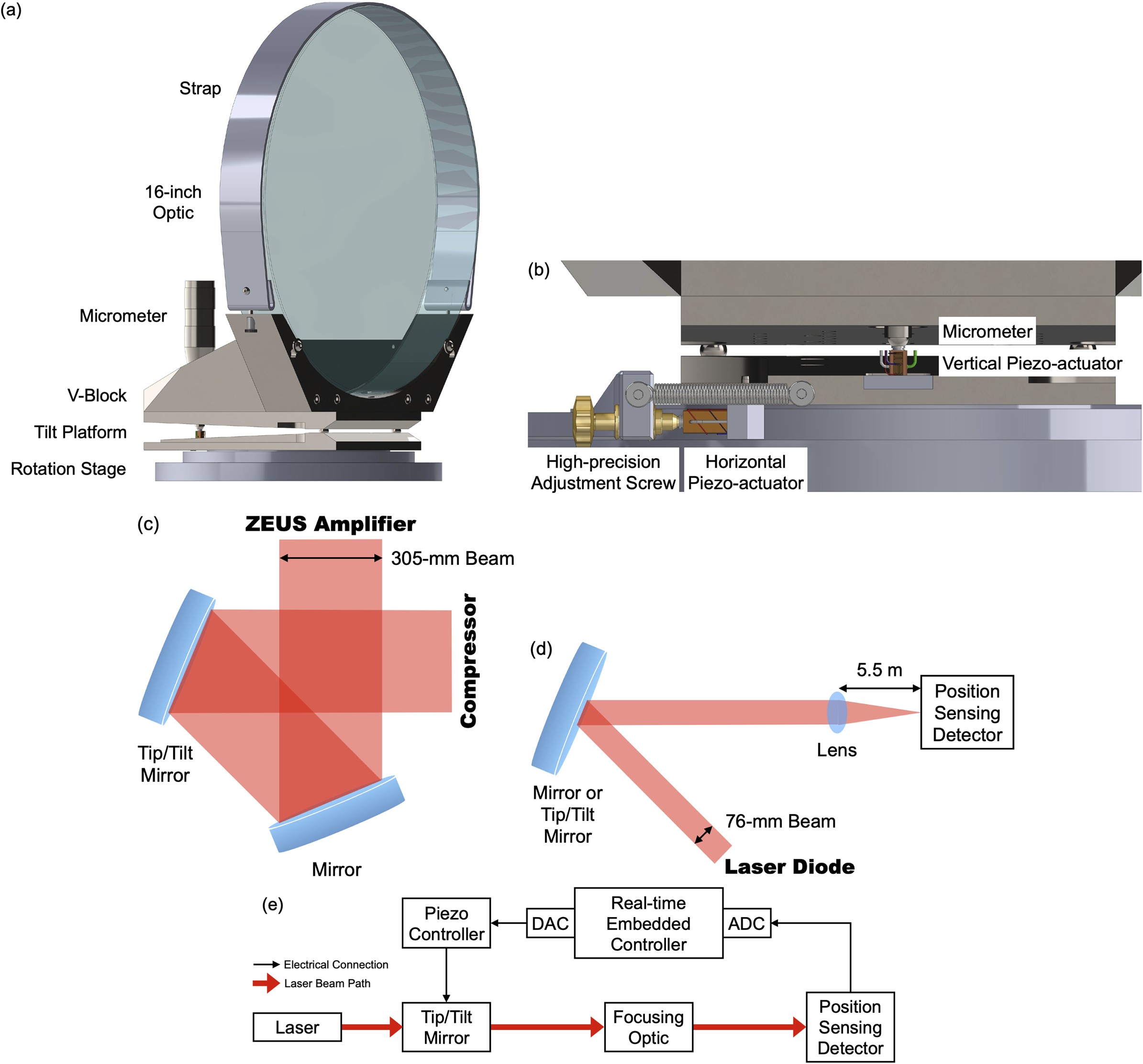
The optics used in this work have a diameter of 16 inches and a thickness of 2 inches. They have a broadband, high-reflective coating on their front surfaces designed for maximum reflectivity at an incident angle of 22.5°. Up to 120-J, 1-ns duration amplified pulses would be steered 90° by the 16-inch mirrors and enter into the 3-PW compressor of the ZEUS laser[ Reference Nees, Maksimchuk, Kalinchenko, Hou, Ma, Campbell, McKelvey, Willingale, Jovanovic, Kuranz, Thomas and Krushelnick20, Reference Willingale, Maksimchuk, Nees, Bayer, Burger, Campbell, Hou, Jovanovic, Kalinchenko, Kuranz, Ma, McKelvey, Thomas, Weinberg, Zhang and Krushelnick21]. As shown in Figure 1(c), the amplified beam is reflected by the original 16-inch mirror with only manual tip/tilt adjustment, followed by the 16-inch fast tip/tilt mirror with piezo-actuators. The original 16-inch mirror assembly was based on an off-the-shelf rotation stage driven by a high-precision adjustment screw and a micrometer-driven tilt platform (Newport Corporation) to realize the manual tip/tilt adjusting mechanism with a low profile. It also consists of a custom stainless steel V-block, a reinforcement block and a thin steel strap to rigidly mount the optics, as shown in Figure 1(a). The total assembly weighs approximately 50 kg. We implemented two measures to increase the resonance frequency of such a heavy assembly through enhancing its stiffness-to-mass ratio (Equation (1)). A flat fused silica substrate ensures the stiffness of the optic and allows beam leakage, compared to a hollowed substrate. The optic is held onto the V-block through the thin steel strap to avoid excess weight around the top portion of the mirror.

Figure 1 Experimental setup. (a) Computer-aided design (CAD) model of the 16-inch mirror assembly. (b) Enlarged view of the horizontal and vertical piezo-actuators. (c) Beam path of amplified ZEUS laser beam turning 90° by two 16-inch mirrors. (d) Beam path of 16-inch mirror testing setup using a laser diode (not to scale). Mirror, original 16-inch mirror assembly without piezo-actuators; tip/tilt mirror, piezo-actuated 16-inch mirror assembly. (e) Schematic of the active control of laser beam pointing.
The 16-inch fast tip/tilt mirror assembly with two piezo-actuators (PC4QMC2, Thorlabs, Inc.) installed against the adjustment screw and micrometer was constructed to demonstrate active control of beam pointing. A modular design was adopted such that the two piezo-actuators with adapter plates could be easily installed or uninstalled (Figure 1(b)). The piezo-actuators have a maximum displacement of approximately 9 μm and 1000 N of blocking force. The calculated resonant frequency of the piezo-actuators under the mechanical load is around 1 kHz. The two piezo-actuators were carefully aligned and centered with the adjustment screw and micrometer to avoid excessive tensile stresses that would lead to their failure. The positions of the piezo-actuators were then fixed with high-temperature epoxy during the first installment.
5 Experimental setup
To study the effects of the ambient environment on the beam-pointing stability, we also employed an apparatus to characterize vibration and temperature simultaneously. Two high-sensitivity, three-dimensional seismic accelerometers (356B18, PCB Piezotronics, Inc.) synchronously measured the vibration on the laboratory floor and the optical table. The accelerometer has a resolution of $5\times {10}^{-5}$
g with a frequency range (±5%) covering 0.5–3000 Hz. We precisely aligned the x-axis and y-axis of the accelerometers along the directions perpendicular and parallel to the optical table chain, respectively, and their z-axis vertically with respect to the optical table surface[
Reference Willingale, Maksimchuk, Nees, Bayer, Burger, Campbell, Hou, Jovanovic, Kalinchenko, Kuranz, Ma, McKelvey, Thomas, Weinberg, Zhang and Krushelnick21]. A temperature logger with 0.024°C resolution was placed on the optical table adjacent to the 16-inch mirror assembly to record the temperature every minute.
$5\times {10}^{-5}$
g with a frequency range (±5%) covering 0.5–3000 Hz. We precisely aligned the x-axis and y-axis of the accelerometers along the directions perpendicular and parallel to the optical table chain, respectively, and their z-axis vertically with respect to the optical table surface[
Reference Willingale, Maksimchuk, Nees, Bayer, Burger, Campbell, Hou, Jovanovic, Kalinchenko, Kuranz, Ma, McKelvey, Thomas, Weinberg, Zhang and Krushelnick21]. A temperature logger with 0.024°C resolution was placed on the optical table adjacent to the 16-inch mirror assembly to record the temperature every minute.
While waiting for the construction of the Ti:sapphire laser beam to be completed, we performed a proof-of-principle study of active beam-pointing control using a CW laser diode at 808 nm (Figure 1(d)). By sampling the CW beam only at 100 Hz, we effectively simulated the operation of the active control system with the Ti:sapphire regenerative amplifier outputs at 100 Hz. The single-mode, polarization-maintaining CW fiber output was first collimated to a 3-inch diameter beam. The collimation and beam profile were verified using a wavefront sensor. The collimated 3-inch beam was then incident on the top portion of the 16-inch mirror assembly (original or piezo-actuated mirror) at 22.5°, and the reflected beam was focused with a lens with a 5.5-m focal length. A two-dimensional, lateral effect position sensing detector (PDP90A, Thorlabs, Inc.) was placed at focus to measure the position of the beam’s centroid. The detector has a bandwidth of 15 kHz and is capable of resolving 0.75-μm displacements, corresponding to an angular resolution of 0.14 μrad. The laser diode, focusing lens and position sensing detector were rigidly mounted on the chain of optical tables holding the ZEUS[
Reference Willingale, Maksimchuk, Nees, Bayer, Burger, Campbell, Hou, Jovanovic, Kalinchenko, Kuranz, Ma, McKelvey, Thomas, Weinberg, Zhang and Krushelnick21]. The beam-pointing instability induced by these three elements is determined to be negligible ( $\sim$
0.1 μrad) compared to that induced by the 16-inch mirror in a baseline study.
$\sim$
0.1 μrad) compared to that induced by the 16-inch mirror in a baseline study.
A simple proportional feedback loop was realized in the onboard field-programmable gate array (FPGA) of a real-time embedded controller (CompactRio, National Instruments), which acquires the position sensing detector outputs as the feedback loop’s error signal inputs and produces the corrected voltage to drive the piezo-actuator. The proportional coefficient ${K}_{\mathrm{P}}$
was carefully adjusted to minimize the standard deviation of angular beam-pointing fluctuations within 1-second windows for both directions. The voltage outputs generated from the position sensing detector were digitized by a 24-bit delta-sigma analog-to-digital converter (ADC, NI-9202), and the corrected voltages calculated by the FPGA were transmitted to a 16-bit string digital-to-analog converter (DAC, NI-9264). The piezo controller (BPC303, Thorlabs, Inc.) amplifies the corrected voltages 15 times and then directly applies the amplified voltage to the piezo-actuators.
${K}_{\mathrm{P}}$
was carefully adjusted to minimize the standard deviation of angular beam-pointing fluctuations within 1-second windows for both directions. The voltage outputs generated from the position sensing detector were digitized by a 24-bit delta-sigma analog-to-digital converter (ADC, NI-9202), and the corrected voltages calculated by the FPGA were transmitted to a 16-bit string digital-to-analog converter (DAC, NI-9264). The piezo controller (BPC303, Thorlabs, Inc.) amplifies the corrected voltages 15 times and then directly applies the amplified voltage to the piezo-actuators.
6 Performance test
We simultaneously characterized the ambient vibration on the floor and optical table with the beam-pointing stability measurement using three-dimensional accelerometers. The power spectral density (PSD) of the measured time series is shown in the Appendix (Figures 7 and 8). The PSD $S(f)$
of a discrete time series
$S(f)$
of a discrete time series ${x}_n$
is defined as follows:
${x}_n$
is defined as follows:
 $$\begin{align}S(f)=\frac{\Delta t}{N}{\left|\sum \limits_{n=0}^{N-1}{x}_n\exp \left(-\mathrm{i}2\pi fn\Delta t\right)\right|}^2,\end{align}$$
where $\Delta t$
is the sampling interval and
$\Delta t$
is the sampling interval and $N$
is the total number of samples. The baseline of the ambient vibration on the floor is determined to be
$N$
is the total number of samples. The baseline of the ambient vibration on the floor is determined to be $1\times {10}^{-12}\ {\mathrm{g}}^2/\mathrm{Hz}$
, which is around two orders of magnitude larger than that reported in the ELI-Beamlines facility[
Reference Borneis, Laštovička, Sokol, Jeong, Condamine, Renner, Tikhonchuk, Bohlin, Fajstavr, Hernandez, Jourdain, Kumar, Modřanský, Pokorný, Wolf, Zhai, Korn and Weber40]. Also, the peak amplitude exceeds the
$1\times {10}^{-12}\ {\mathrm{g}}^2/\mathrm{Hz}$
, which is around two orders of magnitude larger than that reported in the ELI-Beamlines facility[
Reference Borneis, Laštovička, Sokol, Jeong, Condamine, Renner, Tikhonchuk, Bohlin, Fajstavr, Hernandez, Jourdain, Kumar, Modřanský, Pokorný, Wolf, Zhai, Korn and Weber40]. Also, the peak amplitude exceeds the $1\times {10}^{-10}\ {\mathrm{g}}^2/\mathrm{Hz}$
limit specified by the National Ignition Facility (NIF)[
Reference Trummer, Foley and Shaw41]. The above-mentioned considerable ambient vibration levels indicate the necessity for most high-power systems to actively compensate for beam-pointing instabilities induced by ambient vibration.
$1\times {10}^{-10}\ {\mathrm{g}}^2/\mathrm{Hz}$
limit specified by the National Ignition Facility (NIF)[
Reference Trummer, Foley and Shaw41]. The above-mentioned considerable ambient vibration levels indicate the necessity for most high-power systems to actively compensate for beam-pointing instabilities induced by ambient vibration.
The use of a CW laser provides a more comprehensive picture of beam-pointing instability induced by the home-built 16-inch mirror mount in the frequency domain. In Figures 2(a) and 2(b), we show the PSD of the angular deviation sampled at 10 kHz in the horizontal and vertical directions, respectively. Frequencies below 1 Hz dominate both the horizontal and vertical angular deviations. In addition, 33.5 and 44.5 Hz components contribute significantly to the vertical angular deviation. We also observed approximately 10 Hz vibrational components on the optical table transferred to the angular deviation in both directions. However, their effects are negligible compared to the frequency components mentioned above. Figure 2(c) clearly illustrates the significance of each frequency component regarding their contribution to the overall standard deviation of angular beam-pointing fluctuations. The standard deviations of angular pointing fluctuations at different cutoff frequencies are calculated by the following:
 $$\begin{align}\sigma \left({f}_{\mathrm{cutoff}}\right)=\sqrt{\sum \limits_{f_{\mathrm{cutoff}}}^{f_{\mathrm{Nyquist}}}2S(f)\Delta f}, \end{align}$$
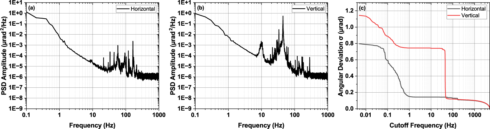
Figure 2 Short-term characterization of the original 16-inch mirror assembly. PSD, power spectral density. (a) Power spectral density of the horizontal angular deviation. (b) Power spectral density of the vertical angular deviation. (c) Comparison of the standard deviation of the horizontal (black) and vertical (red) angular pointing fluctuations, with only frequencies higher than the cutoff frequency contributing to the standard deviation.
where $\sigma$
is the standard deviation,
$\sigma$
is the standard deviation, ${f}_{\mathrm{cutoff}}$
is the cutoff frequency,
${f}_{\mathrm{cutoff}}$
is the cutoff frequency, ${f}_{\mathrm{Nyquist}}$
is the Nyquist frequency (50 Hz in this work, except for characterizing the original 16-inch mirror at 10 kHz, where the Nyquist frequency is 5 kHz),
${f}_{\mathrm{Nyquist}}$
is the Nyquist frequency (50 Hz in this work, except for characterizing the original 16-inch mirror at 10 kHz, where the Nyquist frequency is 5 kHz), $S(f)$
is the PSD, as defined in Equation (2), and
$S(f)$
is the PSD, as defined in Equation (2), and $\Delta f=1/\left(N\Delta t\right)$
is the frequency interval.
$\Delta f=1/\left(N\Delta t\right)$
is the frequency interval.
We determined the cutoff frequencies of the original 16-inch mirror to be 1 and 50 Hz for the horizontal and vertical directions, respectively. The frequency components below the cutoff frequencies contribute to 81% of the total horizontal deviation of 0.796 μrad and 89% of the total vertical deviation of 1.14 μrad.
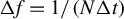
Figure 3 shows the large-signal step response of the piezo-actuated 16-inch mirror assembly characterized by a 2.5-GHz oscilloscope. The square wave generated by a function generator was amplified by the piezo controller with a 20-μs rising edge and then drove the piezo-actuators at their maximum drive voltage (150 V). The piezo-actuated 16-inch mirror assembly reached a steady state in the horizontal direction within approximately 150 ms. In the vertical direction, the mirror resonates for approximately 700 ms with an approximately 23 ms period, corresponding to the major peak at 44.5 Hz shown in Figure 2(b). The 44.5 Hz resonance frequency limits the maximum frequency of beam-pointing instability that could be compensated in our setup; however, this could be mitigated by applying a notch filter at such a frequency in the control algorithm.
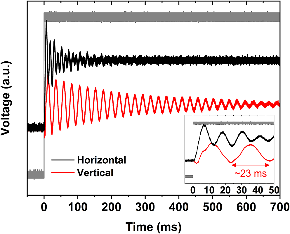
Figure 3 Large-signal step response of the piezo-actuated 16-inch mirror in the horizontal (black) and vertical (red) directions. Grey curve, square wave generated by a function generator; inset, enlarged view of the first 50 ms.
The results of active beam-pointing stabilization with proportional feedback control are shown in Figure 4. In Figure 4(a), the driving voltages were kept constant when no control algorithm was implemented. The proportional feedback control was realized at 100 Hz by sampling the position sensing detector’s output and driving the piezo-actuators at this frequency. When active control was implemented, the nth sampled beam-pointing deviation was corrected by the (n–1)th sample 10 ms earlier. The feedback loop then acquired the deviation of the nth sample to generate the corrected voltage for the (n+1)th sample. Benefiting from the FPGA architecture, the loop execution time was less than 50 μs without any FPGA optimizations, much less than the sampling interval (10 ms). The loop execution time consists of 8.5 μs ADC input delay, 5.3 μs DAC update time and 20 μs controller delay during voltage amplification. The standard deviations of the horizontal and vertical angular pointing fluctuations are 0.798 and 1.15 μrad when piezo-actuators are driven at a constant voltage (without active control), consistent with the performance of the original 16-inch mirror without piezo-actuators. This indicates that incorporating the two piezo-actuators does not deteriorate the mechanical properties of the original 16-inch mirror assembly design, and the electrical noise of the ADC, DAC and piezo controllers is negligible. With proportional feedback control, we demonstrated a 91% reduction to 0.0747 μrad in the horizontal direction and a 78% reduction to 0.254 μrad in the vertical direction, as shown in Figure 4(b). We did not observe significant hysteresis of the piezo-actuators, likely due to the small-signal operating range as a result of the efficacy our control system demonstrated. On the other hand, a feed-forward algorithm could be incorporated to compensate for the actuators’ hysteresis[ Reference Qin, Zhang, Xing, Xu and Li42, Reference Natal, Barber, Isono, Berger, Gonsalves, Fuchs and van Tilborg43].
Figure 4 Short-term time series of the beam-pointing in the horizontal (black) and vertical (red) directions sampled at 100 Hz. (a) Piezo-actuated 16-inch mirror without active control. (b) Piezo-actuated 16-inch mirror with active control.
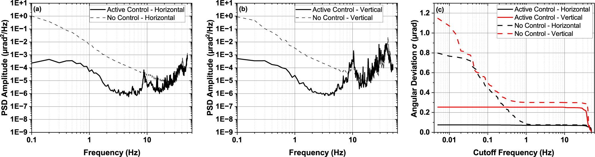
To further study the efficacy of the proportional feedback control, we investigated the PSD and cutoff frequency-dependence of the time series of the piezo-actuated 16-inch mirror shown in Figure 4. The results are shown in Figure 5. The dashed grey curves shown in Figures 5(a) and 5(b) represent the PSD of the angular deviation induced by piezo-actuated mirror without active control and sampled at 100 Hz, which is slightly different from the PSD derived from the characterization of the original 16-inch mirror sampled at 10 kHz (Figures 2(a) and 2(b)). With the proportional feedback control, Figures 5(a) and 5(b) illustrate at least two orders of magnitude suppression at frequencies lower than approximately 5 Hz and more than three orders of magnitude suppression at the low-frequency end in both directions. Figure 5(c) further demonstrates the efficacy of the active control method by comparing the cutoff frequency-dependent angular deviation with and without proportional feedback control. In the vertical direction, we are able to compensate all the frequency components up to the mirror’s resonance frequency at 44.5 Hz. All the frequency components lower than the Nyquist frequency were compensated in the horizontal direction. We believe the small residual in the horizontal direction was due to the convolution of the vertical direction since the laser was incident on the mirror at 22.5°.

Figure 5 Short-term characterization of the piezo-actuated 16-inch mirror assembly. PSD, power spectral density. (a) Power spectral density of horizontal angular deviation with (solid black) and without (dashed grey) active control. (b) Power spectral density of vertical angular deviation with (solid black) and without (dashed grey) active control. (c) Comparison of the standard deviation of horizontal (black) and vertical (red) angular pointing fluctuations, with only frequencies higher than the cutoff frequency contributing to the standard deviation.
Managing long-term beam-pointing jitter induced by ambient environmental change is also required for high-power laser systems, since the beam-pointing jitter can significantly deteriorate the experimental results after the initial alignment. As a result, we first studied the beam-pointing jitter of the original 16-inch mirror over 48 hours (Figure 6(a)). The beam-pointing was sampled at 100 Hz; nonetheless, we only show one point per second for clarity in Figure 6. We observed a considerable deviation in the vertical direction up to 23 μrad and a 7.6 μrad change in the horizontal direction with only 0.6°C temperature variation. We believe this is due to the difference between the thermal expansion coefficient of the different stainless steel components, which is the material of both our customized and off-the-shelf parts. The original 16-inch mirror assembly experienced relaxation and re-equilibrium during the temperature changes. We completely eliminated the long-term beam-pointing jitter with the same proportional feedback control operating at 100 Hz, as shown in Figure 6(b). With a larger temperature variation of 0.8°C and more random fluctuation, the standard deviation of the horizontal and vertical beam-pointing jitter is reduced to 0.085 and 0.29 μrad, respectively. The long-term stabilization results further demonstrate the robustness of our control method.
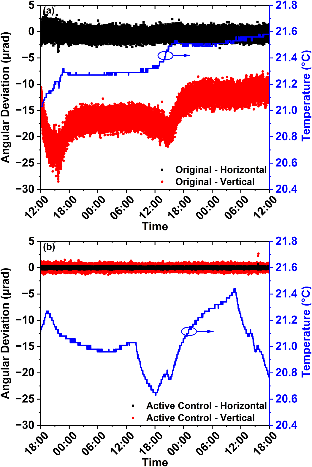
Figure 6 Long-term (48-hour) stability characterization of two 16-inch mirror assemblies in the horizontal (black) and vertical (red) directions. The temperature fluctuation is plotted as the blue curve. (a) Original 16-inch mirror design. (b) Actively controlled piezo-actuated 16-inch mirror assembly.
7 Conclusion
In summary, we demonstrated an actively controlled 16-inch mirror in a high-power laser system. Active control of the beam pointing with large optics is of vital importance for a wide range of experiments facilitated with a high-power laser system such as ZEUS. With two piezo-actuators and a simple FPGA-based proportional feedback control, we reduced the short-term beam-pointing instability by up to an order of magnitude, from (0.798, 1.15) to (0.0747, 0.254) μrad in the (horizontal, vertical) direction, providing an adequate margin from the beam-pointing requirement of a few μrad. The long-term drift due to temperature variation was also eliminated. Given the considerable baseline of ambient vibration reported in the ZEUS facility, our approach manifests its effectiveness, although it is limited by the resonance frequency of the optics assembly, which could be mitigated by implementing a notch filter in the control algorithm. To integrate the presented active beam-pointing control system in ZEUS, an online and non-destructive diagnostic at the focus[ Reference Isono, van Tilborg, Barber, Natal, Berger, Tsai, Ostermayr, Gonsalves, Geddes and Esarey35] of a PW-class laser is necessary and can be challenging to implement. A mechanical shutter with a few-millisecond close time is also needed to block the amplified beam from the diagnostics so that the position sensing detector only detects the unamplified beam after proper attenuation.
It would be beneficial in future work to fine-tune the resonance frequency of the 16-inch mirror assembly to a frequency higher than the Nyquist frequency of the active control system, assisted by FEA. With such a mechanical design improvement, our proportional feedback control could potentially compensate for beam-pointing instabilities up to the Nyquist frequency, which is 50 Hz in the scheme described in this work. The performance of the control system could be improved by analyzing and optimizing its frequency response and gain using a mathematical model and incorporating integral and derivative terms into the feedback loop. Data-driven recurrent neural network models such as long short-term memory and the gated recurrent unit could also be employed to improve the efficacy of the feedback control[ Reference Breitling, Weigel, Downer and Tajima44, Reference Chang, Ge, Wang, Yuan and Fan45]. However, a substantial amount of data from the actual laser shots must be collected to train such models.
Appendix: Ambient vibration measured in the ZEUS facility
The ambient vibrations on the floor (Figure 7) and optical table (Figure 8) in the ZEUS facility were simultaneously characterized along with the beam-pointing stability measurement using three-dimensional accelerometers. The standard deviations of the ambient vibration on the floor in the x, y and z directions are $2.41\times {10}^{-4}$
,
$2.41\times {10}^{-4}$
, $1.65\times {10}^{-4}$
and
$1.65\times {10}^{-4}$
and $2.10\times {10}^{-4}$
g, respectively, whereas the values increased to
$2.10\times {10}^{-4}$
g, respectively, whereas the values increased to $2.77\times {10}^{-4}$
,
$2.77\times {10}^{-4}$
, $1.83\times {10}^{-4}$
and
$1.83\times {10}^{-4}$
and $3.02\times {10}^{-4}$
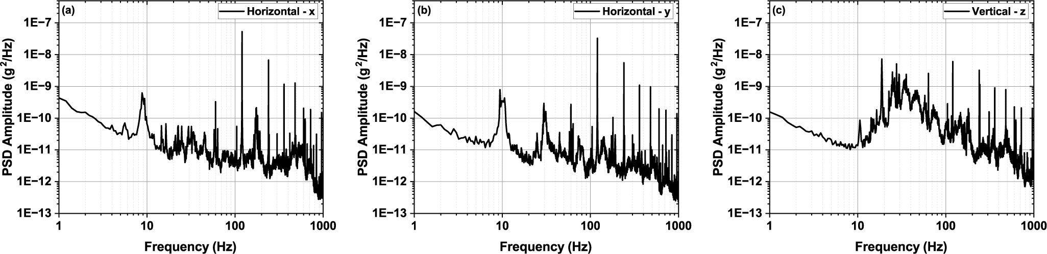
g on the optical table. As shown in Figure 8, in the horizontal directions x (perpendicular to the main laser chain) and y (parallel to the main laser chain), frequencies below 2 Hz, at 9 and 60 Hz, are prominent in the PSD below 100 Hz. We aim our attention at frequency components lower than 100 Hz due to the
$3.02\times {10}^{-4}$
g on the optical table. As shown in Figure 8, in the horizontal directions x (perpendicular to the main laser chain) and y (parallel to the main laser chain), frequencies below 2 Hz, at 9 and 60 Hz, are prominent in the PSD below 100 Hz. We aim our attention at frequency components lower than 100 Hz due to the $1/{f}^2$
scaling law for displacement regarding the frequency. Other laser facilities have also identified a cutoff frequency lower than 100 Hz (see, for example, Refs. [Reference Isono, van Tilborg, Barber, Natal, Berger, Tsai, Ostermayr, Gonsalves, Geddes and Esarey35, Reference Tang, Guo, Yang, Jiang, Hua and Zong37]). The 30 Hz component in the y direction also contributes significantly. In the z direction (vertical to the table surface), a broader frequency range between 14 and 83 Hz has a significant contribution in addition to the frequencies below 2 Hz.
$1/{f}^2$
scaling law for displacement regarding the frequency. Other laser facilities have also identified a cutoff frequency lower than 100 Hz (see, for example, Refs. [Reference Isono, van Tilborg, Barber, Natal, Berger, Tsai, Ostermayr, Gonsalves, Geddes and Esarey35, Reference Tang, Guo, Yang, Jiang, Hua and Zong37]). The 30 Hz component in the y direction also contributes significantly. In the z direction (vertical to the table surface), a broader frequency range between 14 and 83 Hz has a significant contribution in addition to the frequencies below 2 Hz.
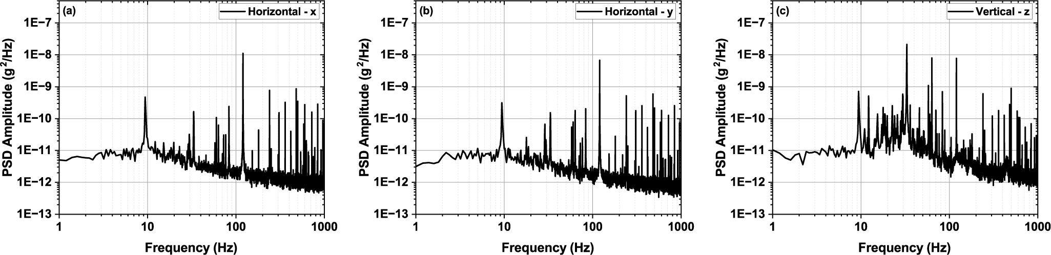
Figure 7 Ambient vibration measured on the floor near the 3-PW compressor in the ZEUS facility. PSD, power spectral density. (a) Horizontal direction perpendicular to the main laser chain. (b) Horizontal direction parallel to the main laser chain. (c) Vertical direction.

Figure 8 Ambient vibration measured on the optical table of the main laser chain in the ZEUS facility. PSD, power spectral density. (a) Horizontal direction perpendicular to the main laser chain. (b) Horizontal direction parallel to the main laser chain. (c) Vertical direction.
Acknowledgements
We acknowledge support from the U.S. National Science Foundation Mid-scale Research Award 1935950, the U.S. National Science Foundation Award 2126181, and the U.S. Department of Energy grant DE-SC0016804.


 Open access