


1 Introduction
Ultrafast Raman fiber lasers provide an effective method to achieve picosecond or femtosecond pulses with wavelength flexibility, while also leveraging the advantages of fiber lasers, including a compact structure, high beam quality and excellent stability[ Reference Zhou, Pan, Qi, Cao, Cheng and Feng 1 – Reference Chen, Chen, Jiang, Yin and Hou 3 ]. In contrast to rare-earth-doped fiber lasers, which are limited in output wavelength by the emission spectrum of dopant ions, Raman fiber lasers theoretically offer the potential to generate any desired wavelength across the transparency window of optical fibers by appropriately selecting the pump wavelength[ Reference Deheri, Dash, Supradeepa and Balaswamy 4 – Reference Zhang, Song, Ye, Xu, Yao and Zhou 6 ].
Among various techniques, mode-locking and synchronous pumping are the most commonly used methods for generating ultrafast Raman pulses. Both material-based and artificial saturable absorbers have been widely utilized to initialize and stabilize ultrafast pulses in mode-locked Raman fiber lasers[ Reference Castellani, Kelleher, Travers, Popa, Hasan, Sun, Flahaut, Ferrari, Popov and Taylor 2 , Reference Chamorovskiy, Rautiainen, Lyytikäinen, Ranta, Tavast, Sirbu, Kapon and Okhotnikov 7 – Reference Kobtsev 13 ]. However, pumped by low-intensity continuous wave (CW) light, fiber of tens or even hundreds of meters is required to achieve sufficient Raman gain, leading to significant dispersion and nonlinearity in the oscillator. In order to solve the problem of the long fiber cavity, replacing the CW pump with a pulsed one could be an effective approach to obtain adequate Raman gain with a shorter cavity length. Implementing synchronous pumping could be a promising solution to realize highly coherent Raman pulse output. Yet, for achieving resonance enhancement, the repetition rate of the pulsed pump has to match the total length of the Raman resonant cavity, which means that an additional optical delay line is necessary to realize synchronization between the pump and Raman pulses[ Reference Chen, Chen, Jiang, Yin and Hou 3 , Reference Babin, Podivilov, Kharenko, Bednyakova, Fedoruk, Kalashnikov and Apolonski 14 – Reference Kobtsev, Kukarin and Kokhanovskiy 16 ]. Meanwhile, the pulse energy is restricted to the nJ level by the oscillator structure in these two methods.
An amplifier structure based on directly pumping a piece of optical fiber offers a simpler and more compact design to achieve repetition-rate flexibility and high Raman pulse energy. However, the Raman pulse originating from the spontaneous Raman emission shows low coherence due to the short Raman dephasing time in fused silica of 32 fs[ Reference Lefrançois and Wise 17 ], exhibiting noise-like pulse (NLP) characteristics[ Reference Zhao, Pan, Zeng and Feng 18 ]. When there exists a coherent seed for Raman fiber amplification, the generated Stokes pulses could demonstrate excellent compressibility. In 2018, Chen et al. [ Reference Chen, Xu, Ge, Gao, Fan, Song, Liu, Li, Wang and Hu 19 ] proposed a self-seeding method in which a novel ultrafast Raman fiber amplifier could generate 67 nJ, 76 fs nearly transmission-limited Raman pulses. The spectrum of the input pump pulse was expanded to approximately 1100 nm through self-phase modulation (SPM)-induced spectrum broadening, and then the longer wavelength components served as the coherent seed. To further scale up the Raman pulse energy and the optical conversion efficiency, Liu et al. [ Reference Liu, Xu, Zhao, Zhang, Ci and Li 20 ] demonstrated an optimized structure that increases the single pulse energy and conversion efficiency to 2.56 μJ and 89.5%, respectively.
In self-seeded Raman fiber amplifiers, it is important to control the pulse width of the initial pulse to ensure that the SPM-induced spectral broadening is sufficiently powerful. Otherwise, spontaneous Raman scattering noise would become amplified instead of the coherent spectral components, especially for pulses with transmission-limited pulse duration greater than 10 ps. Recently, nonlinear optical gain modulation (NOGM) has been proven to be an excellent technique to obtain an all-fiber-based femtosecond laser with both repetition-rate and wavelength agility[ Reference Cheng, Zhou, Cao, Cui, Jiang and Feng 21 ]. A single-frequency continuous wave (SF-CW) laser could be converted to femtosecond-scale Raman pulses, which are amplified and gain modulated by the ultrafast pump pulses. In previously reported NOGM systems, the pump pulse energy boosting unit and nonlinear frequency conversion unit are separated. For example, the ultrafast pulsed pump is typically amplified to a certain energy level in the rare-earth-doped fiber, and then injected into a piece of passive fiber with the SF-CW seed to complete the NOGM process[ Reference Cheng, Zhou, Cao, Cui, Jiang and Feng 21 – Reference Qi, Zhou, Cao, Cheng, Li, Jiang, Cui and Feng 24 ]. However, two main issues might exist in the previously reported configurations: firstly, a wavelength division multiplexer (WDM), which combines the high-power pulsed pump and the SF-CW seed, would be a demanding fiber component for further power scaling; secondly, the fusion splice between the active fiber and the passive fiber operating at high power can also pose a risk to the long-term stability of the system.
Here, we report an integrated ultrafast Yb-Raman fiber amplifier that delivers approximately 1 μJ Raman pulses with a compressed pulse duration of 589 fs and a Raman conversion efficiency of 69.9%, which represents the highest pulse energy output recorded in the NOGM system. In this structure, low-power pump pulses and the SF-CW seed are simultaneously injected into a piece of ytterbium-doped fiber (YDF), enabling both pump pulse amplification and the NOGM process, which eliminates the need for the high-power WDM and avoids the fusion splice between the passive and active fibers. Further numerical simulation results indicate that the YDF gain for spectral components over 1100 nm enhances the 1121 nm Raman pulse energy within a short fiber length. Due to the reduced accumulation of nonlinear chirp, the generated Raman pulses exhibit improved time-domain characteristics. Meanwhile, the potential for generating 10 μJ level Raman pulses using the integrated Yb-Raman fiber amplifier was also demonstrated numerically.
2 Experimental setup and simulation model
In a typical NOGM system, an SF-CW laser, serving as the seed, is amplified and reshaped in a piece of optical fiber. The optical fiber could provide nonlinear optical gain through stimulated Raman scattering (SRS), which is pumped by an ultrafast pulse train. The ultrafast pump laser would act as a modulation driver, offering a gain modulation to reshape the SF-CW signal. Further, the SF-CW signal would be modulated into a pulse train synchronized with the pulsed pump.
A schematic of the integrated ultrafast Yb-Raman fiber amplifier based on NOGM is shown in Figure 1(a). A 10 mW, 1121 nm SF-CW diode (LD-PD Inc., PL-DFB-1120-A-A81-PA) with a 110 kHz linewidth served as the seed, ensuring the high coherence of the generated Raman pulses. The pump source is a commercial gain switched diode (GSD, QD Laser, QCED106G-6410) with a center wavelength of 1065 nm, whose repetition rate is determined by an electrical trigger signal and is set at 10 MHz in this experiment. It was pre-amplified to over 150 mW before being coupled with the SF-CW seed by a 1064/1120 nm WDM. The combined pump and seed were then injected into an ytterbium-doped fiber amplifier (YDFA), consisting of a 976 nm multi-mode laser diode (MM-LD) and a 2.4-m-long YDF (Nufern, PLMA-YDF-10/125-M). In the front section of the YDF, the pump pulse energy was further boosted to exceed the Raman conversion threshold. Then, the 1121 nm SF-CW seed was amplified and gain modulated to the Raman pulses in the backend section of the YDF. Notably, the 1121 nm spectral components received optical gain from both SRS and the YDF in the entire process. Compared with the conventional NOGM system, such a hybrid Yb-Raman gain scheme can lead to improved performance of generated Raman pulses, which is confirmed by the following experimental and simulation results.
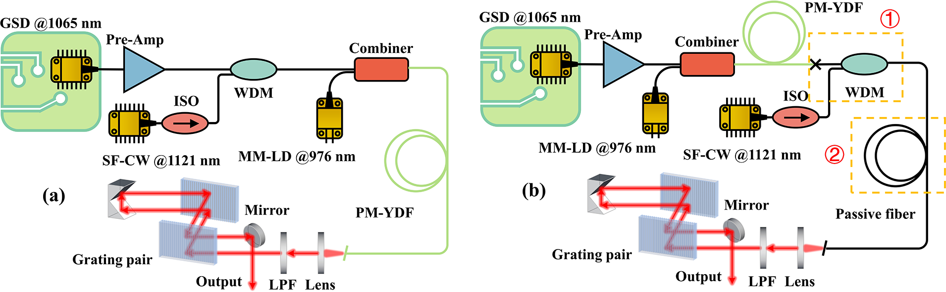
Figure 1 Schematic of two different NOGM structures. (a) Integrated NOGM Yb-Raman fiber amplifier. (b) Traditional NOGM Raman fiber amplifier.
Figure 1(b) shows a typical NOGM schematic previously reported, where the pump pulses were amplified to sufficient energy before coupling with the SF-CW seed to complete the NOGM process in a piece of passive fiber. There are two main differences from the integrated ultrafast Yb-Raman fiber amplifier demonstrated above, which is highlighted as the orange dashed boxes in Figure 1(b). For dashed box #1, temperature rise due to the splicing loss between the passive and active fibers would pose a significant challenge under high-power operation, along with the requirement for a high-power WDM. Another difference exhibited in dashed box #2 is that the NOGM process is primarily performed in the passive fiber for the previous demonstration.
In the experiment, the pulse characteristics were evaluated using commercially available instruments. The output power was determined with power meters (Thorlabs S146C and S425C-L). The optical spectra were captured using an optical spectrum analyzer (Yokogawa AQ6370D) with a fine resolution of 0.02 nm. The pulse duration was measured with a commercial autocorrelator (APE PulseCheckSM1200). For pulse train observations, a real-time oscilloscope (Keysight DS090254A, 2.5 GHz bandwidth) was employed, while the repetition rate was recorded using a radio-frequency (RF) spectrum analyzer (Keysight N9020A, 26.5 GHz bandwidth).
To further investigate the Yb-Raman fiber amplifier, a comprehensive simulation study was conducted. The Raman response function could be included in the generalized nonlinear Schrödinger equation (GNLSE), which has been widely applied for simulating the pulse evolution as a foundational and versatile mathematical framework[ Reference Hult 25 , Reference Dudley and Coen 26 ]. This numerical model includes a second-order dispersive effect, SPM, self-steepening and SRS, along with gain provided by the YDF:
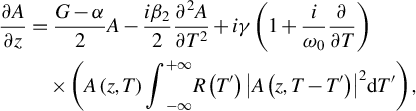 $$\begin{align}\frac{\partial A}{\partial z}&=\frac{G-\alpha }{2}A-\frac{i{\beta}_2}{2}\frac{\partial^2A}{\partial {T}^2} + i\gamma \left(1+\frac{i}{\omega_0}\frac{\partial }{\partial T}\right)\nonumber\\& \quad \times \left(A\left(z,T\right){\int}_{-\infty}^{+\infty }R\left({T}^{\prime}\right){\left|A\left(z,T-{T}^{\prime}\right)\right|}^2\mathrm{d}{T}^{\prime}\right), \end{align}$$
where A(z,T) represents the slowly varying envelope, z denotes the propagation distance, ω
0 is the chosen reference frequency and T is the local time of the pulse. The first and second terms on the right-hand side of Equation (1) account for the linear propagation effects, where G is the gain coefficient, $\alpha =0$
represents the linear power attenuation and β
2 = 0.024 ps2/m accounts for the group velocity dispersion. The third term describes nonlinear optical effects, where γ = 0.0023 m–1 W–1 is the nonlinear coefficient and R(T) represents the nonlinear response function, which could be described as follows[
Reference Qi, Zhou, Cui, Cheng, Zeng and Feng
22
]:
$\alpha =0$
represents the linear power attenuation and β
2 = 0.024 ps2/m accounts for the group velocity dispersion. The third term describes nonlinear optical effects, where γ = 0.0023 m–1 W–1 is the nonlinear coefficient and R(T) represents the nonlinear response function, which could be described as follows[
Reference Qi, Zhou, Cui, Cheng, Zeng and Feng
22
]:
 $$\begin{align}R(T)&=\left(1-{f}_{\mathrm{R}}\right)\delta (T)+{f}_{\mathrm{R}}{h}_{\mathrm{R}}(T)\nonumber\\& =\left(1-{f}_{\mathrm{R}}\right)\delta (T)+{f}_{\mathrm{R}}\frac{\tau_1^2+{\tau}_2^2}{\tau_1{\tau}_2^2}\exp \left(\!\!-\frac{T}{\tau_2}\right)\sin \left(\!\frac{T}{\tau_1}\right)\Theta (T),\end{align}$$
where f R = 0.18 represents the fractional contribution of the delayed Raman response, τ 1 = 12.2 fs and τ 2 = 32 fs, δ(T) is the Dirac delta function and Θ(T) is the Heaviside step function. Notably, amplification in the YDF including the effect of gain-induced spectral filtering is considered in the frequency domain using the Lorentzian line shape with 40 nm bandwidth, while the gain saturation is determined by G = G 0/(1+E p/E sat). Here, G 0 is the small gain coefficient of the YDF while E p and E sat represent the local pulse energy and saturable energy, respectively. In this model, the gain saturation could be adjusted to imitate varying pump power[ Reference Sidorenko and Wise 27 ].
3 Results and discussion
3.1 Experimental results
The pulse evolution process was investigated at the repetition rate of 10 MHz with the pump power increasing from 1.77 to 26.0 W. The measured spectral and autocorrelation trace evolutions are depicted in Figures 2(a) and 2(b), respectively. With the pump power increasing, the 1065 nm pump energy was first transferred to the 1121 nm Stokes light, resulting in the pulse breaking of pump pulse. Both the spectrum bandwidth and pulse duration of first-order Stokes light gradually broadened until the dominance of the second-order Raman conversion. Figure 2(c) depicts the scheme of the temporal evolution of the pump and Raman pulses. The SF-CW seed is gain modulated to the ultrafast Raman pulses and then starts to transfer to the next order Stokes light, which limits the output energy. Due to the intensity-dependent characteristic of SRS, the conversion began first at the peak of the pump pulses, leading to the pulse breaking with increasing intervals between the split pulses, which corresponds to the growing distance between the side peaks and the center of the autocorrelation curve shown in Figure 2(b). What differs from the conventional NOGM system with passive fiber is that both the pump and the Stokes light were amplified by the YDF throughout the entire process, which enabled achieving higher Raman pulse energy output within a shorter fiber length. Figure 2(d) reflects the ratio of the pump, the first-order Stokes and second-order Stokes pulse energy to the total energy. To calculate the power ratio of the pump pulses and the Stokes pulses, the spectrum was first converted to linear coordinates, followed by spectral integration over different wavelength bands. The spectral integration ranges for the pump pulse, the first-order Stokes light and the second-order Stokes light are 1050–1080, 1080–1150 and 1150–1200 nm, respectively. It was found that 18.3 ps, 986 nJ Raman pulses at 1121 nm could be achieved with a Raman conversion efficiency of 69.9% when the total pulse energy is boosted to 1.41 μJ. Further increase of the pump power results in the emergence of second-order Stokes light, which would lead to energy conversion and pulse splitting of the 1121 nm light, as shown by the blue line in Figures 2(a) and 2(b).
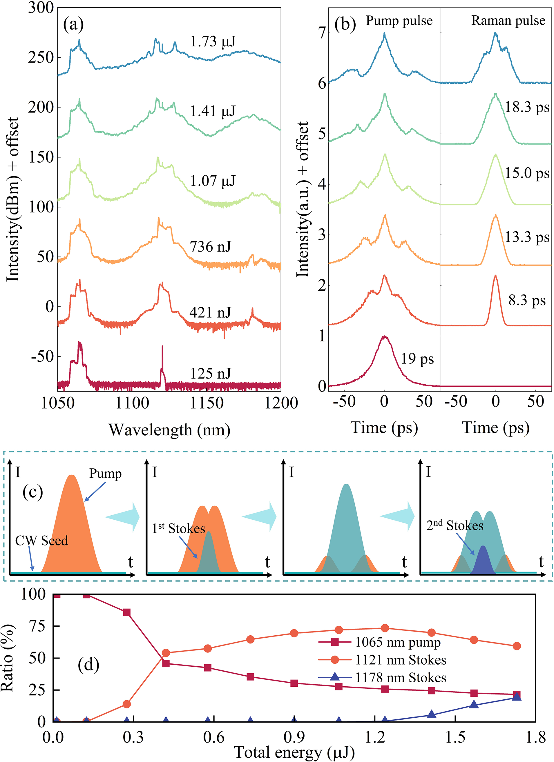
Figure 2 Pulse evolution at the repetition rate of 10 MHz. (a) Spectral and (b) autocorrelation trace evolution versus the pulse energy. (c) Schematic of temporal evolution of the pump and Raman pulses. (d) Ratio of the pump, first-order Stokes and second-order Stokes pulse energy versus the total energy.
The SF-CW seed with high spectral coherence is an essential component in the NOGM setup. Without the SF-CW seed, the random noise would also be amplified and modulated by the pulsed pump, resulting in Raman pulses with large phase noise, which are referred to as NLPs. For comparison, the output Raman pulse characteristics have been measured with and without the 1121 nm SF-CW laser injection. With the SF-CW seed, the Raman pulses exhibited steep spectral edges on both sides, as depicted in Figure 3(a). When the average power (energy) of the pulse was amplified to 14.1 W (1.41 μJ), the Raman conversion efficiency (Raman pulse energy) reached 69.9% (986 nJ). Figure 3(b) shows that the 1121 nm Raman pulse could be compressed to 589 fs by the grating pair, while the pulse width before compression was approximately 18.3 ps. However, a pedestal could be observed at the compressed pulse autocorrelation curve, primarily due to the incomplete compensation of the nonlinear chirp. Figure 3(c) presents the measured pulse train with a period of 100 ns, corresponding to the RF spectrum recorded at 10 MHz in Figure 3(d), with a signal-to-noise ratio (SNR) of approximately 81.1 dB.

Figure 3 The first-order Stokes pulse characteristics with and without SF-CW seed input. With the SF-CW seed input: (a) spectrum; (b) autocorrelation trace of the compressed pulse (inset: before compression); (c) pulse train; (d) radio-frequency spectrum with a resolution of 10 Hz (inset: zoom-out spectrum). Without the SF-CW seed input: (e) spectrum; (f) autocorrelation trace; (g) pulse train; (h) radio-frequency spectrum with a resolution of 10 Hz (inset: zoom-out spectrum).
In the absence of SF-CW injection, the random noise could be regarded as the seed source. As shown in Figure 3(e), the noise within the Raman gain spectrum was also amplified, resulting in a broader spectrum around 1121 nm. Simultaneously, the pulse conversion efficiency decreased to 30.3%. As illustrated in Figure 3(f), the autocorrelation curve exhibited a wide pedestal and a narrow central spur, which are typical features of NLPs. Figure 3(g) indicates that, due to the randomness of the noise, the intensity fluctuations of the newly generated pulse train were more pronounced, reflecting lower intensity stability. The SNR of the RF spectrum decreased to 67.4 dB (Figure 3(h)), confirming the importance of the high-coherent seed injection.
To further enhance the first-order Stokes pulse energy, it is crucial to prevent energy transfer from the first-order Stokes pulses to the second-order Stokes pulses, which could be achieved by applying a 1065 nm pump pulse with larger pulse width and YDF with a larger core diameter. In the following numerical simulations, we explored these methods to increase the first-order Stokes pulse energy.
3.2 Simulation results
In the above experiment, approximately 1 μJ 1121 nm Raman pulses could be achieved, marking the highest pulse energy output recorded in an NOGM system. Encouraged by the experimental results, a comprehensive simulation study was conducted to further investigate the advantages of the Yb-Raman hybrid gain fiber amplifier.
The simulated NOGM setup strictly follows the experimental one, which was injected by 15 nJ and 19.0 ps transform-limited sech2-shape pulses based on the characteristics of the pre-amplified GSD pulses. Then, the pulse experienced amplification and the NOGM process within a piece of 3-m-long YDF. Two different gain models were compared: one in which spectral components over 1100 nm were amplified by SRS and the YDF, referred to as the integrated ultrafast Yb-Raman fiber amplifier (Scenario1, S1), and another in which these components were amplified solely by SRS (Scenario2, S2). The evolutions of the pump and the Stokes pulse energy in both conditions in the 3-m-long YDF are illustrated in Figure 4. When the fiber length was set to 2.4 m and the YDF gain was provided for a wavelength surpassing 1100 nm, the energy of the first-order Stokes light reached the maximum output of 1098 nJ, achieving a conversion efficiency of 83.1%, which was higher than the experimental results. This could be attributed to the low-intensity amplified spontaneous emission (ASE) noise in the GSD pump that was isolated from converting to the first-order Stokes pulse[ Reference Cheng, Zhou, Cao, Cui, Jiang and Feng 21 ]. Further increasing the YDF length, the emergence of the second-order Stokes components subsequently reduced the energy of the first-order Stokes pulse.
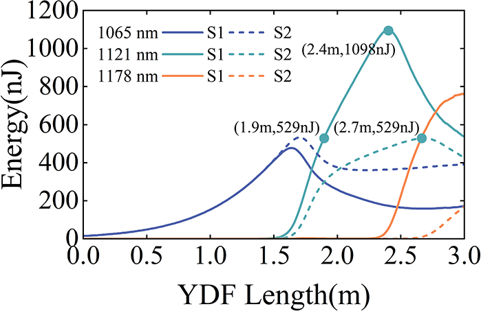
Figure 4 Evolution of pulse energy in the 3 m YDF. The solid line (S1) represents spectral components over 1100 nm with gain from both the YDF and SRS, while the dashed line (S2) indicates spectral components over 1100 nm with gain only from SRS. The blue line corresponds to the 1065 nm pump pulse, the green line represents the 1121 nm Stokes pulse and the orange line denotes the 1178 nm Stokes pulse.
In contrast, if there was no YDF gain over 1100 nm, the maximum energy of the first-order Stokes pulse energy could only achieve 529 nJ with a longer YDF length of 2.7 m and lower Raman conversion efficiency of 57.6%. Regardless of whether YDF gain was present over 1100 nm, when the fiber length was less than 1.5 m, amplification primarily occurs for the 1065 nm pump pulse. Subsequently, the generation of first-order Stokes light was observed at nearly the same position in both cases. However, without YDF gain for the first-order Stokes light, its energy growth was significantly slower, resulting in a lower slope in the curve. This is mainly because, without YDF gain, the first-order Raman conversion process was slower, leading to the amplification of the 1065 nm pump light before reaching maximum Raman conversion efficiency, which reduced the proportion of the first-order Stokes pulse energy.
Figure 5 illustrates the temporal evolution of pulses in both scenarios. Figures 5(a) and 5(b) show the evolution of the pump pulse. For YDF lengths shorter than 1.5 m, pump pulse amplification was the dominant process. When Raman conversion occurred, and YDF gain was available for wavelength over 1100 nm, the leading and trailing edges of the pump pulse were consumed at a similar rate. In contrast, when the first-order Stokes light lacked the support of YDF gain, the trailing edge of the pump pulse remained amplified. Figures 5(c) and 5(d) depict the temporal evolution of the first-order Stokes light, offering further insight into this behavior. When YDF gain was present over 1100 nm, the temporal evolution of the first-order Stokes light was relatively symmetrical, with both the leading and trailing edges absorbing energy from the corresponding regions of the pump pulse. In the absence of YDF gain, the temporal center of the first-order Stokes light gradually shifted toward the leading edge of the pump pulse due to the walk-off effect between the pump pulse and the first-order Stokes pulse[ Reference Qi, Zhou, Cao, Cheng, Jiang, Cui and Feng 28 ]. However, the trailing edge of the pump pulse continued to transfer energy to the trailing edge of the Stokes pulse, resulting in a broader trailing edge of the Stokes pulse, which accounts for the temporal asymmetry.
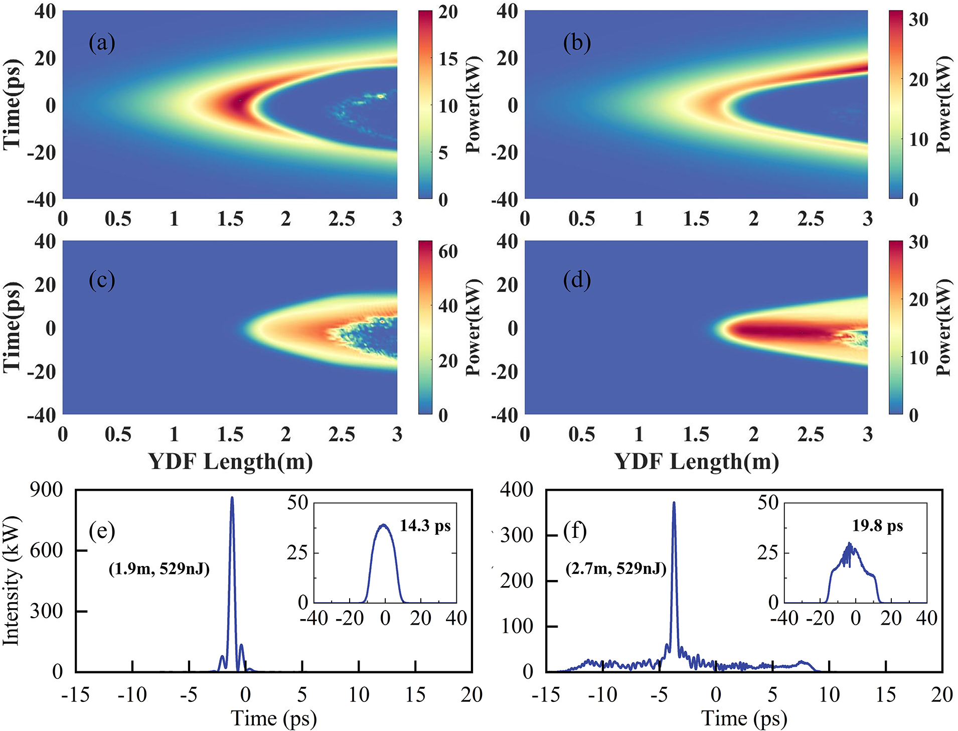
Figure 5 Temporal evolution of the pump pulse and the first-order Stokes pulse (left-hand column: YDF gain was present for wavelengths over 1100 nm; right-hand column: YDF gain was absent for wavelengths over 1100 nm). (a), (b) Evolution of the pump pulse. (c), (d) Evolution of the first-order Stokes pulse. (e), (f) Temporal profile after compression and before compression (the inset figure) when achieving 529 nJ Raman pulse energy.
It is worth noting that the YDF length required for the first-order Stokes pulse to reach 529 nJ was approximately 1.9 and 2.7 m in the cases with and without YDF gain over 1100 nm, respectively. Furthermore, the accumulation of different nonlinear effects results in varying pulse characteristics. Figures 5(e) and 5(f) represent the temporal profile of the first-order Stokes pulse in both scenarios. When YDF gain was present over 1100 nm, the first-order Stokes pulse reached the same energy over a shorter YDF length, resulting in a smaller accumulated nonlinear phase shift and a weaker walk-off effect with the pump light. This led to a more symmetric time-domain pulse shape, with a pulse width of approximately 14.3 ps. In contrast, when YDF gain was absent, the longer YDF length led to second-order Raman conversion, causing a dip at the top of the pulse. In addition, the pulse exhibits an asymmetric shape, with the pulse width increasing to 19.8 ps. As both pulses were then compressed to approximately 500 fs, it can be observed that in the presence of rare-earth gain, the accumulated nonlinear chirp was more significant, resulting in incomplete chirp compensation, forming a pedestal of approximately 20 ps that accounts for approximately 54.9% of the total energy, thus reducing the performance of the laser.
As shown in Figure 3, the SF-CW seed has a critical impact on the performance of the first-order Stokes light, and hence we further investigated the influence of the SF-CW seed power on the characteristics of the amplifier. Previously reported research has indicated that insufficient seed power would lead to decreased Raman conversion efficiency and poor coherence due to the Raman gain competition between the SF-CW seed and the amplified spontaneous Raman emission[ Reference Cheng, Zhou, Cao, Cui, Jiang and Feng 21 ]. Here, we primarily investigated the condition under which the seed source power was set at 10, 50, 100 and 200 mW, respectively. As the SF-CW seed power increases from 10 to 200 mW, the Raman conversion efficiency also increases from 83.1% to 87.9%, but with the maximum first-order Stokes pulse energy remaining at around 1.1 μJ. The increase in the SF-CW seed power facilitates the output of first-order Stokes pulses with a shorter length of fiber, but it also leads to the earlier generation of second-order Stokes pulses.
Finally, we want to emphasize here that further boosting the Raman pulse energy up to the 10 μJ level is feasible with the optimized system parameters. Figure 6 represents the results when the pump pulse width was set to 60 ps and the nonlinear coefficient was set to 0.0011 m –1 W –1, corresponding to a mode-field diameter of approximately 14.5 μm. As shown in Figure 6(a), the second-order Raman scattering limits the further amplification of the first-order Raman pulse. At the fiber length of 1.66 m, an 11.6 μJ, 1121 nm Raman pulse could be achieved with an optical conversion efficiency of 83.5%. The Raman pulse shows a 3.78 nm spectral width and a 77.6 ps pulse duration that could be compressed to 930 fs (Figures 6(b) and 6(c)). The results indicate that by applying a pump pulse with higher pulse energy, larger pulse width and YDF with a larger core diameter (smaller nonlinear coefficient), the output pulse energy of the hybrid gain NOGM system can be further increased by more than 10 times. Such a high pulse energy femtosecond laser with flexible wavelength can effectively promote application expansion of ultrafast Raman fiber lasers.

Figure 6 Characteristics of the first-order Stokes pulse with 11.6 μJ pulse energy. (a) Spectral evolution in the 2-m-long YDF. (b) Pulse spectrum and (c) temporal profile after compression and before compression (the inset figure) at the length of 1.66 m.
4 Conclusions
In summary, we demonstrated an integrated Yb-Raman fiber amplifier that produces high-energy Raman pulses through a hybrid amplification method, achieving approximately 1 μJ Raman pulse energy output at 1121 nm, the highest Raman pulse energy recorded in an NOGM system. The experimental results revealed that the introduction of the SF-CW seed significantly enhances pulse characteristics, leading to high-quality Raman pulses with efficient noise suppression. Comparative numerical analysis between scenarios with and without YDF gain for spectral components over 1100 nm highlighted the critical role of the YDF gain in influencing the energy and temporal evolution of both pump and Stokes pulses. The presence of YDF gain for Raman pulses not only accelerated the first-order Stokes pulse generation but also improved the Raman pulse temporal performance. In contrast, the lack of YDF gain for spectral components over 1100 nm resulted in slower conversion rates, requiring a longer fiber length to achieve equivalent energy output. Increased fiber length results in greater walk-off effect and accumulation of nonlinear chirp, leading to highly asymmetric temporal output. In addition, the compressed pulse exhibits a pedestal that occupies a significant portion of the pulse energy, due to incomplete compensation of the nonlinear chirp. Meanwhile, it was confirmed that a 10 μJ level femtosecond-level Raman pulse could be achieved by applying a pump pulse with higher pulse energy and YDF with a larger core diameter. Our experiment underscores the potential of utilizing hybrid amplification schemes in NOGM systems, providing a pathway for further investigations into enhancing Raman amplification. These findings pave the way for the development of high pulse energy femtosecond lasers with flexible wavelength, expanding their applications in various fields, such as material processing and biomedical imaging.
Acknowledgements
The work is supported by the National Key R&D Program of China (Grant No. 2024YFB3907802); the Youth Innovation Promotion Association of the Chinese Academy of Sciences (Grant No. 2022247); the National Natural Science Foundation of China (Grant Nos. 62175244, 62075226, 12341404 and 62305358); and the Natural Science Foundation of Shanghai (Grant No. 21ZR1472200).


 Open access