


1 Introduction
High-peak-power femtosecond lasers possess significant application prospects in fields such as high harmonics generation[ Reference Fang and Liu1], terahertz science[ Reference Guan, Li, Wu, Liu, Ma, Zhao, Wang, Liu, Zhang, Cao and Li2] and attosecond science[ Reference He, He, Sun, Goetz, Le, Zhu, Lan, Lu and Lin3– Reference Hu, Yu, Cao, Chen, Zou, Yin, Sheng and Shao6]. Chirped pulse amplification (CPA) has been widely employed in femtosecond pulse amplifiers due to its capability to significantly reduce the peak power during amplification, thereby effectively mitigating the risk of optical damage to the gain medium[ Reference Strickland and Mourou7– Reference Chen, Zheng, Lu, Wang, Cai, Wang, Zheng, Ai, Leng, Xu and Fan9]. Historically, Ti:sapphire lasers have been the prototypical representative of this technology. Although the broad gain bandwidth of Ti:sapphire supports the generation of femtosecond pulses of the order of optical cycles, its power scalability is limited by the low-power Q-switched green pump source and high quantum defects[ Reference Golinelli, Chen, Bussière, Gontier, Paul, Tcherbakoff, D’Oliveira and Hergott10, Reference Nishimiya, Noda and Suda11].
In recent years, the development of femtosecond lasers based on ytterbium (Yb)-doped gain media has opened new possibilities for achieving high-power radiation[ Reference Shen, Song, Peng, Gao, Zhu, Liu and Leng12, Reference Gao, Song, Peng, Shen, Zhu, Liu and Leng13]. The absorption wavelength of Yb-doped gain media is well matched to the emission wavelength of InGaAs laser diodes (LDs), which not only significantly reduces system costs but also ensures sufficient pump power. Moreover, their high quantum efficiency and excellent thermal conductivity provide substantial advantages in thermal management[ Reference Viana, Petit, Gaumé, Goldner, Druon, Balembois and Georges14]. Ytterbium-doped yttrium aluminum garnet (Yb:YAG) has become the most widely used gain medium in Yb-based laser systems, owing to its well-established fabrication process and exceptional thermo-optic properties[ Reference Jung, Tümmler and Will15, Reference Nubbemeyer, Kaumanns, Ueffing, Gorjan, Alismail, Fattahi, Brons, Pronin, Barros, Major, Metzger, Sutter and Krausz16]. At a repetition rate of 1 kHz, Yb:YAG lasers based on thin-disk amplification have achieved pulse energies exceeding the joule level[ Reference Wang, Chi, Baumgarten, Dehne, Meadows, Davenport, Murray, Reagan, Menoni and Rocca17]. However, the narrow gain bandwidth of Yb:YAG, coupled with gain narrowing effects during amplification, presents challenges for generating high-energy pulses at the sub-500 fs level[ Reference Schulz, Riedel, Willner, Mans, Schnitzler, Russbueldt, Dolkemeyer, Seise, Gottschall, Hädrich, Duesterer, Schlarb, Feldhaus, Limpert, Faatz, Tünnermann, Rossbach, Drescher and Tavella18– Reference Hong, Gopinath, Rand, Siddiqui, Huang, Li, Eggleton, Hybl, Fan and Kärtner20]. Other Yb-doped anisotropic crystals have demonstrated strong potential for generating high-peak-power pulses. Figure 1 summarizes the amplified pulse parameters achieved with different crystals based on a regenerative amplifier (RA). For Yb:KGd(WO4)2 (Yb:KGW), He et al. [ Reference He, Yu, Zhu, Guo, Zhou and Ruan21] demonstrated femtosecond pulses with a duration of 227 fs and an energy of 1.2 mJ using a dual-crystal amplification scheme. For Yb:KY(WO4)2 (Yb:KYW), Delaigue et al. [ Reference Delaigue, Manek-Honninger, Honninger, Courjaud and Mottay22] achieved femtosecond pulses with a duration of 480 fs and an energy of 1 mJ at 5 kHz. However, the relatively low thermal conductivity and limited saturation fluence of Yb:KGW and Yb:KYW make it difficult to further scale up the peak power of the femtosecond pulses. Although Yb:CaYAlO4 (Yb:CALYO) exhibits similar crystal properties to Yb:CaGdAlO4 (Yb:CALGO), it is typically supplied by research institutes or universities and has not been well commercialized. Both Yb:CaF2 and Yb:LiYF4 (Yb:YLF) have the potential to generate high-peak-power lasers. For example, in 2024 a Yb:CaF2 laser was reported to have achieved femtosecond pulses with an energy of 10.3 mJ and a duration of 257 fs[ Reference Zhang, Li, Li, Xu, Zhang, Niu, Sui, Yuan, Liu, Ma, Wang, Zhang, Bai, Li and Fan23]. The output energy of a Yb:YLF-based RA can reach 20 mJ, while a scheme incorporating multi-pass amplification can achieve up to 100 mJ[ Reference Pergament, Kellert, Demirbas, Thesinga, Reuter, Liu, Hua, Kilinc, Yakovlev and Kärtner24, Reference Demirbas, Cankaya, Hua, Thesinga, Pergament and Kärtner25]. However, the implementation of a cryogenic cooling system further increases the complexity and cost of the system.
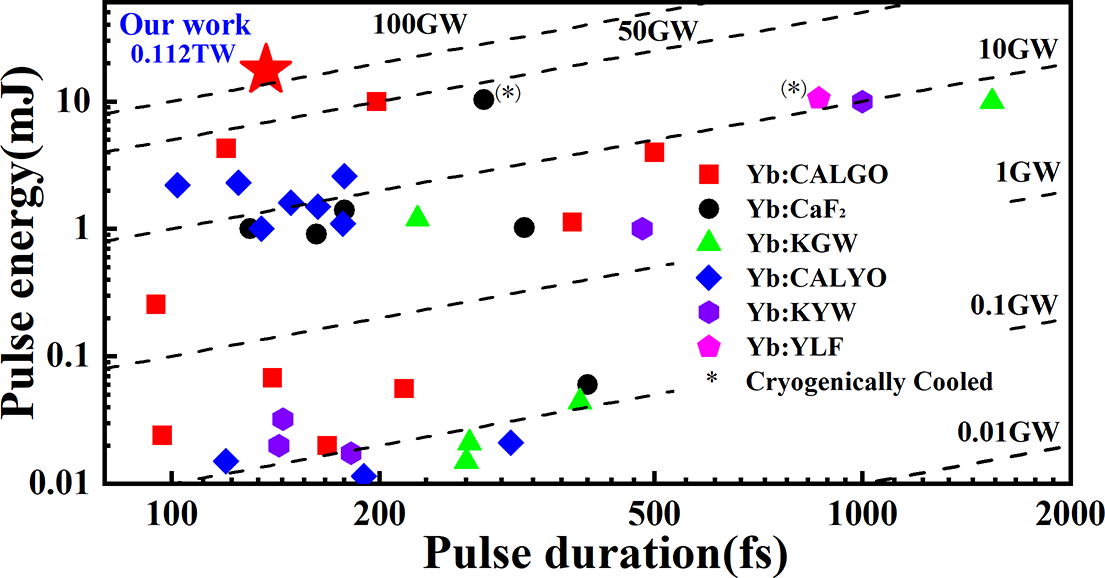
Figure 1 Summary of pulse duration and output energy for Yb-doped bulk-crystal regenerative amplifiers.
Compared to the aforementioned crystals, Yb:CALGO features a broader emission bandwidth (~80 nm), a superior thermal conductivity and a large saturation energy density, offering potential for generating high-peak-power pulses[ Reference Wang, Pan, Meng, Liu and Shen26, Reference Wang, Bai, Zheng, Tian, Mai, Yu, Tian, Wei and Zhu27]. Wang et al. [ Reference Wang, Wu, Liu, Sun and Liang28] employed a double-end pumping configuration to amplify a single Yb:CALGO crystal, achieving an output pulse duration of 95 fs and demonstrating the capability of Yb:CALGO to support sub-100 fs pulse generation. Zhu et al. [ Reference Zhu, Song, Peng, Shen, Gao, Liu and Leng29], by combining a dual-crystal configuration with a quasi-continuous-wave (CW) pumping scheme, achieved pulse energies of up to 10 mJ and durations of 198 fs at 1 kHz, resulting in a peak power approaching 50 GW, marking the highest peak power ever reported for RA based on bulk crystals at room temperature. However, the system is still constrained by the spectral bandwidth of the seed source, the stretching capacity of the pulse stretcher and the damage threshold of the gain medium. We believe this does not represent the peak power/energy output limit of Yb:CALGO-based RA systems.
In this work, we demonstrate a dual-crystal RA based on Yb:CALGO, delivering a peak power of up to 112 GW. Benefiting from a thermally insensitive cavity design and a quasi-CW pumping scheme, we have achieved a maximum pulse energy of 21.01 mJ. Under conditions that prevent crystal damage, the system stably delivers compressed pulses with an energy of 17.6 mJ and a pulse duration of 137 fs. A power stability of 0.506% was maintained over 30 minutes. The measured beam quality factors are M 2 = 1.16 × 1.12. To the best of our knowledge, this represents the highest pulse energy and peak power ever achieved from a Yb:CALGO crystal by RA, as illustrated in Figure 1.
2 Experimental setup
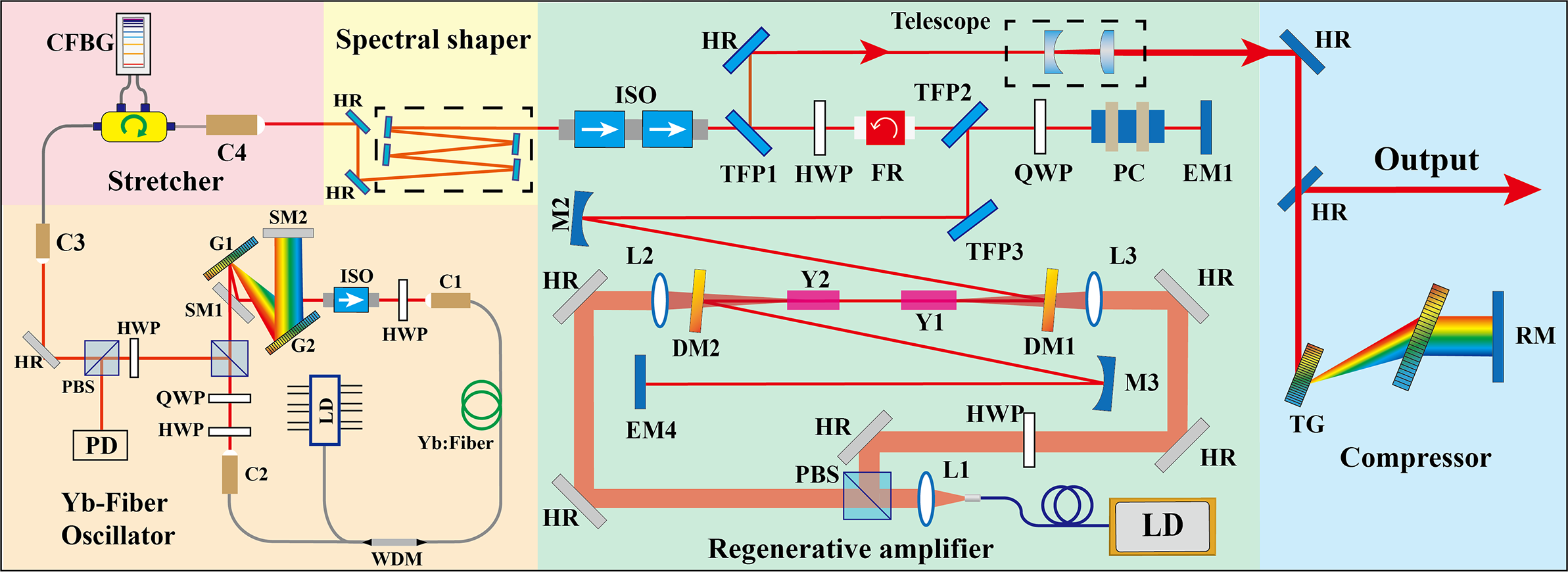
The layout of the Yb:CALGO dual-crystal bulk RA is shown in Figure 2. It primarily consists of five parts: a home-built mode-locked seed source, a fiber-based stretcher, a set of spectral-shaping mirrors, a Yb:CALGO dual-crystal RA and a transmission grating (TG)-based compressor.

Figure 2 Experimental setup of the 112 GW Yb:CALGO RA. C1–C4, collimators; SM1 and SM2, silver mirrors; HWP, half-wave plate; QWP, quarter-wave plate; G1 and G2, reflective blazed gratings; LD, laser diode; WDM, wavelength division multiplexer; PBS, polarization beam splitter; CFBG, chirped fiber Bragg grating; ISO, isolator; TFP1–TFP4, thin-film polarizers; FR, Faraday rotator; PC, Pockels cell; DM1 and DM2, dichroic mirrors; HR, high-reflectivity mirror; EM1 and EM4, end mirrors; Y1 and Y2, Yb:CALGO crystals; RM, roof mirror; TG, transmission grating; L1–L3, lenses; PD, photodiode.
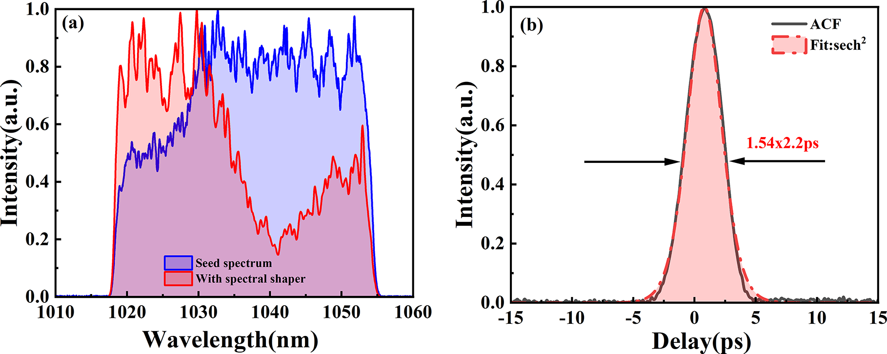
The seed source is a homemade NPE mode-locked fiber oscillator. The pump source of the seed is a single-mode LD with a central wavelength of 976 nm, which is coupled into the gain fiber (Yb1200, LIEKKI) through a wavelength division multiplexer (WDM). A pair of reflective blazed gratings with a groove density of 600 lines/nm is employed to provide negative dispersion. The seed dispersion can be tuned by adjusting the separation between the gratings. At an incident angle of 40° and a grating separation of 63 mm, the net dispersion is close to zero, enabling dispersion-managed soliton mode-locking[ Reference Tamura, Ippen, Haus and Nelson30]. The spectrum of the seed ranges from 1018 to 1056 nm, with a full width at half maximum (FWHM) of approximately 33 nm and a central wavelength of 1036 nm, as shown in Figure 3(a) (blue curve). Compared to our previous publication[ Reference Zhu, Song, Peng, Shen, Gao, Liu and Leng29], the spectral bandwidth becomes broader, which helps increase the peak power of the amplified pulse. The pulse duration is measured by an intensity autocorrelator (PulseCheck-50, A.P.E. GmbH). The shortest pulse duration is 2.2 ps, assuming a sech2 pulse shape, as shown in Figure 3(b). The repetition rate and the output average power of the seed source are 45.60 MHz and 120 mW, respectively.

Figure 3 (a) Comparison of the seed spectrum with (red) and without (blue) the spectral shaper. (b) Autocorrelation curve (black line) and sech2 fitted curve (red line).
In the stretcher part, a circulator is used to couple the seed source and the collimator (C4). A chirped fiber Bragg grating (CFBG) (TPSR, TeraXion) is chosen as the stretcher due to its advantages of compact size, high mobility and absence of spatial chirp. The minimum reflectivity over the operation bandwidth is 77.9%, and the reflection spectrum ranges from 1018 to 1056 nm, with an FWHM of 36 nm. To minimize the risk of laser-induced damage to optical components during amplification, and considering the maximum size of commercially available compression gratings, the group delay dispersion (GDD) of the CFBG is designed to be 17 ps2. Correspondingly, the chirp rate is 29.85 ps/nm, which theoretically allows the seed spectrum to be stretched to over 800 ps.
Before being injected into the RA cavity, the seed is first pre-shaped by four specially designed spectral-shaping mirrors (as shown in Figure 3(a), red curve) to compensate for gain narrowing during amplification and to achieve shorter pulse durations. Each mirror exhibits 70% reflectivity at 1040 nm with approximately 10 nm FWHM. Then, the seed passes through two optical isolators to prevent the amplified pulses affecting the mode-locking.
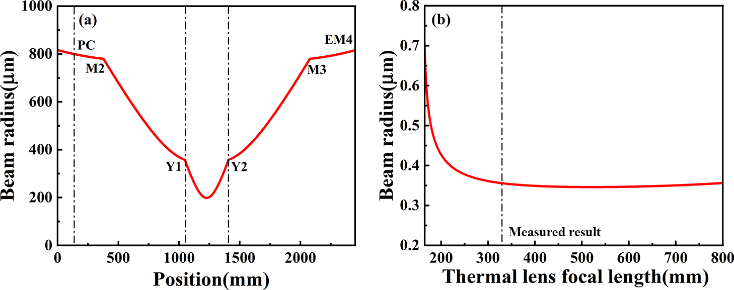
The RA cavity consists of four concave mirrors (EM1, M2, M3, EM4), two dichroic mirrors (DM1, DM2), two thin-film polarizers (TFP2, TFP3) and two Yb:CALGO crystals (Y1, Y2). Both Yb:CALGO crystals have dimensions of 3 mm × 3 mm × 10 mm, a doping concentration of 2% and are oriented along the a-cut. Based on our previous measurement results[ Reference Zhu, Song, Peng, Shen, Gao, Liu and Leng29], in order to avoid laser-induced damage to the crystal and the Pockels cell (PC) and to ensure a pulse output of 20 mJ, we designed the cavity mode at the crystal to be 720 μm and that at the PC to be 1600 μm. The cavity length is 2.46 m, corresponding to a pulse amplification period of 16.4 ns. The cavity mode distribution at a pump power of 410 W is shown in Figure 4(a). By measuring the spot size of the leakage light at the end mirror, we estimated the thermal focal length of the crystal to be approximately 330 mm. For the RA, one of the key aspects is thermal management. To minimize the impact of heat on the output pulse quality to the greatest extent possible, we have taken the following measures. (i) The RA cavity is designed to be thermally insensitive. Figure 4(b) shows the variation of the beam radius at the crystal position with respect to the thermal lens focal length. It can be observed that the beam radius at the crystal remains nearly constant over a wide range of focal lengths. (ii) The dual-crystal amplification scheme reduces the pump power density encountered by each individual crystal, thereby mitigating the effect of thermal lensing. (iii) The pump beam is operated in quasi-CW mode, with the pulse duration set to 550 μs in this experiment[ Reference Zhu, Song, Peng, Shen, Gao, Liu and Leng29]. (iv) The crystals are indium-soldered onto specially designed copper water-cooled heat sinks, which can efficiently dissipate the heat from the crystals and reduce thermal accumulation.

Figure 4 (a) Cavity mode distribution of the dual-crystal Yb:CALGO RA cavity at a pump power of 410 W. (b) Dependence of the beam radius in the Yb:CALGO crystal on the thermal lens focal length. The black line represents the thermal focal length of the crystal measured at a pump power of 410 W, which is 330 mm.
The pump source is a wavelength-stabilized LD with a central wavelength of 981 nm, featuring multi-mode fiber coupled output with a numerical aperture of 0.22 and a core diameter of 200 μm. The maximum output power is 430 W with random polarization. The pump beam is collimated by lens L1, then split into two beams by the polarization beam splitter (PBS) and focused onto two crystals, resulting in a spot size of 750 μm. The beam expansion ratio is 1:3.75. The vertically polarized pump beam is rotated to horizontally polarized by a half-wave plate (HWP). The polarization directions of both pump beams are parallel to the c-axis of the Yb:CALGO, maximizing the utilization of the high absorption cross-section. The polarization direction of the seed is aligned with the a-axis, to achieve a broad spectrum and narrow pulse width with high energy output. The repetition rate of the RA cavity is fixed at 1 kHz. The following results are measured under this condition.
In the compressor part, a pair of TGs with a groove density of 1739.1 lines/mm is employed to compress the amplified pulses.
3 Experimental results
Firstly, we adjust the end mirrors (EM1, EM4) and the pump high-reflectivity (HR) mirrors in CW mode to optimize the output power of the RA cavity. Once the output power is optimized, we insert the PC and adjust its orientation to ensure that the insertion loss is less than 1%. Subsequently, the seed is aligned with the output beam of the RA cavity. Then, we use a digital delay generator to synchronize the seed, PC and pump source, enabling regenerative amplification.
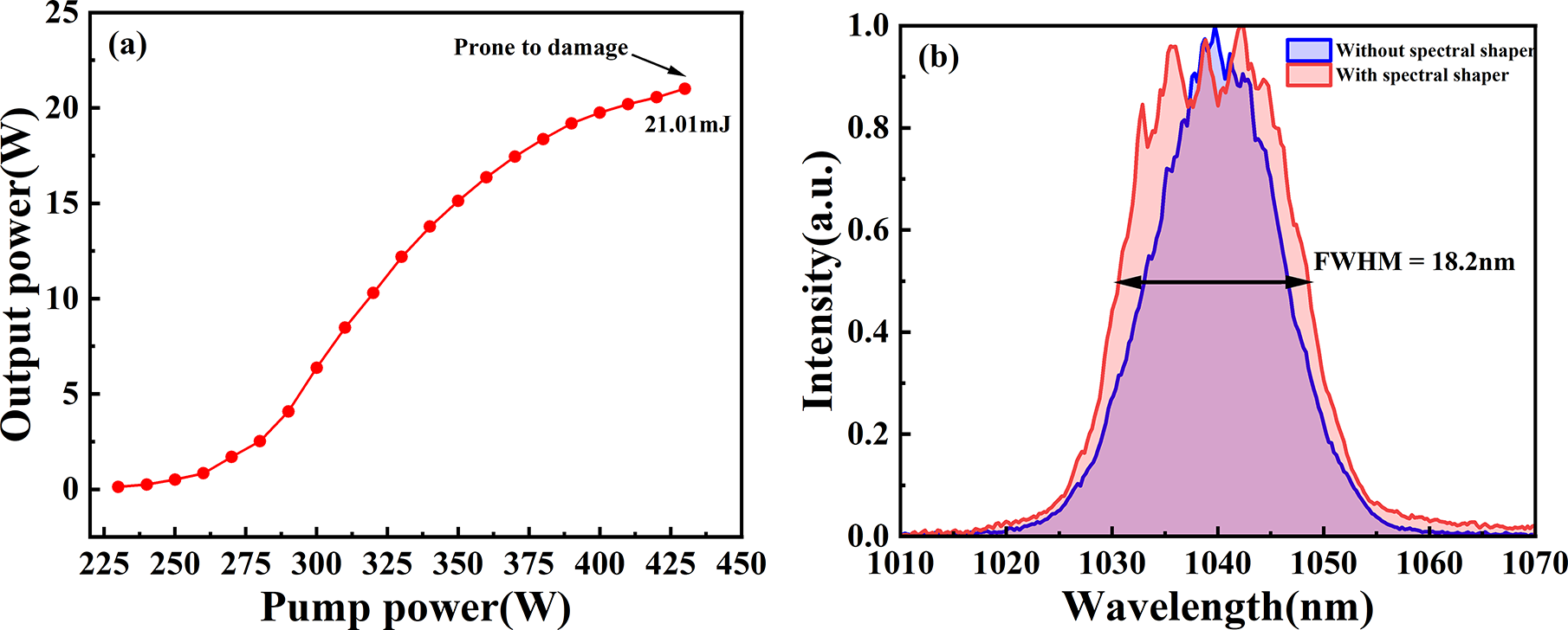
Figure 5(a) shows the curve of output power versus pump power. Due to the large pump spot diameter at the crystals, the pump power density is reduced, resulting in a high amplification threshold for this cavity configuration. Amplification becomes noticeable on the power meter once the pump power exceeds 230 W. When the pump power increases from 280 to 380 W, the output power increases rapidly. As the pump power continues to increase to 430 W, the growth rate slows down, indicating that the amplification capability of this cavity configuration is approaching saturation. However, due to the damage threshold limitation of the crystal’s antireflection coating, the crystals are likely to experience damage at a pulse energy of 21.01 mJ. Therefore, improving the coating technology of the crystal is key to further increasing the pulse energy.

Figure 5 (a) Output power as a function of pump power. The crystal becomes prone to damage at a pump power of 430 W. (b) Amplified spectra with and without the spectral-shaping mirror. The FTL pulse duration is reduced from 120 to 86 fs. The FWHM of the amplified spectrum with the spectral-shaping mirror is 18.2 nm.
To ensure stable operation of the RA and prevent crystal damage, all subsequent measurements were conducted at a pump power of 410 W, corresponding to a pulse energy of 20.10 mJ. Figure 5(b) demonstrates the amplified spectrum. The blue line represents the amplified spectrum without the spectral shapers, while the red line represents the amplified spectrum with the spectral shapers. The spectral bandwidth increased from 13.6 to 18.2 nm, while the Fourier transform limit (FTL) pulse duration decreased from 120 to 86 fs.
At end mirror EM1, the leaked light was detected by a photodiode (PD) and monitored by an oscilloscope, revealing the amplification build-up process, as shown in Figure 6(a). As the seed undergoes more round trips in the RA cavity, the output power gradually increases. The regenerative cycle is approximately 16.4 ns, which is consistent with the length of our cavity. The gate width of the PC is approximately 660 ns, corresponding to 40 round trips in the cavity. At TFP1, the scattered light from the amplified pulse is monitored using another PD, as shown in Figure 6(b) (blue line). By carefully adjusting the quarter-wave plate, as well as the gate width and orientation of the PC, a temporal contrast ratio close to 880:1 was achieved. The intensity of the pre-pulse is shown in the inset of Figure 6(b) (red line).
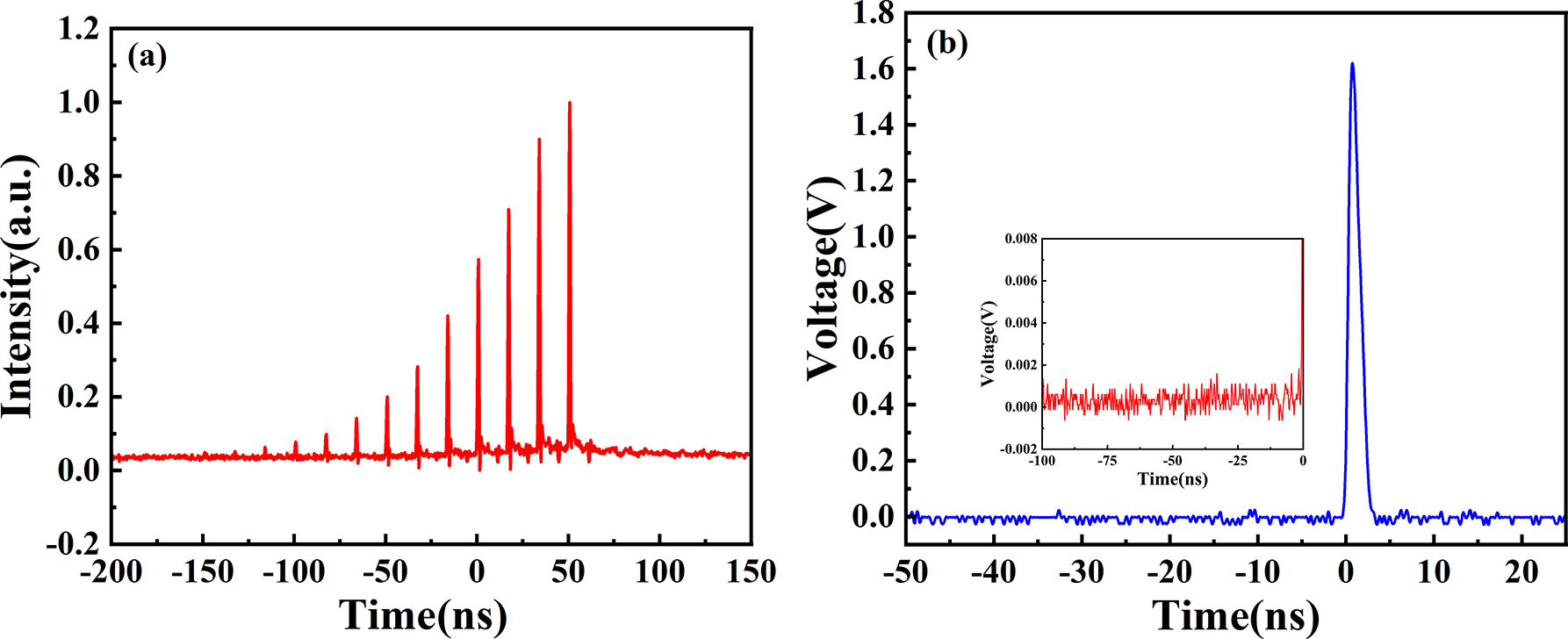
Figure 6 (a) Regenerative amplification process. (b) Temporal contrast of the output pulse.
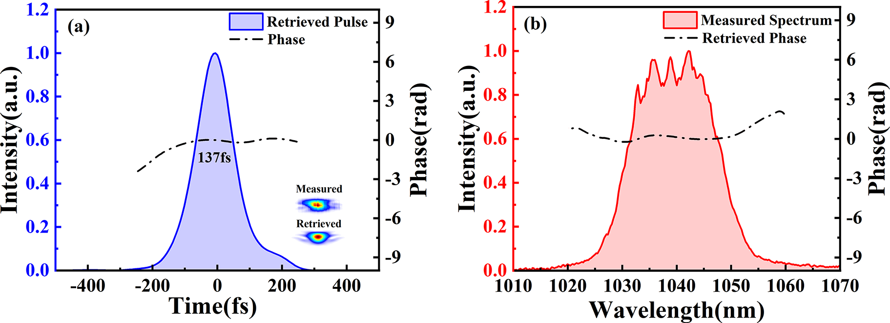
After beam expansion using a 1:3 telescope, the pulse was compressed with a pair of TGs. The compression efficiency is 87.5%. Under conditions where the crystal remains undamaged (with a pulse energy of 20.10 mJ before compression), an output energy of 17.6 mJ was achieved after compression. A home-built second-harmonic generation frequency-resolved optical gating (SHG-FROG) setup was employed to measure and characterize the compressed pulse. Figure 7(a) shows the retrieved pulse duration and temporal phase, while Figure 7(b) presents the measured spectrum and the retrieved spectral phase. The error between the retrieved and measured results is of the order of 4 × 10⁻³. The shortest pulse duration achieved was 137 fs, which is 51 fs broader than the FTL of 86 fs. According to our analysis, there are two main factors. Firstly, additional higher-order dispersion and nonlinear phase shifts in the fiber seed source reduce the compressibility of the amplified pulse. Secondly, the imperfect matching of higher-order dispersion between the CFBG and the TG prevents the compressed pulse from approaching the FTL. Ultimately, we achieved a peak output power of 0.112 TW, which, to the best of our knowledge, is the highest peak power ever obtained based on the Yb:CALGO crystal.

Figure 7 (a) The retrieved pulse (blue), temporal phase (black) and the measured and retrieved FROG traces (inset). (b) The measured spectrum (red) and retrieved spectral phase (black).
The power stability of the RA cavity is shown in Figure 8(a), with a root-mean-square (RMS) variation of 0.506% over 30 minutes. This stability is attributed to the well-designed cavity and effective thermal management. Beam quality was assessed using a commercial M 2 analyzer (BSQ-SP300, Ophir). Figure 8(b) presents the M 2 measurement results, with values of 1.16 in the horizontal direction and 1.12 in the vertical direction. The near-field and far-field beam profiles are shown in Figure 7(b), both showing ideal Gaussian distributions.
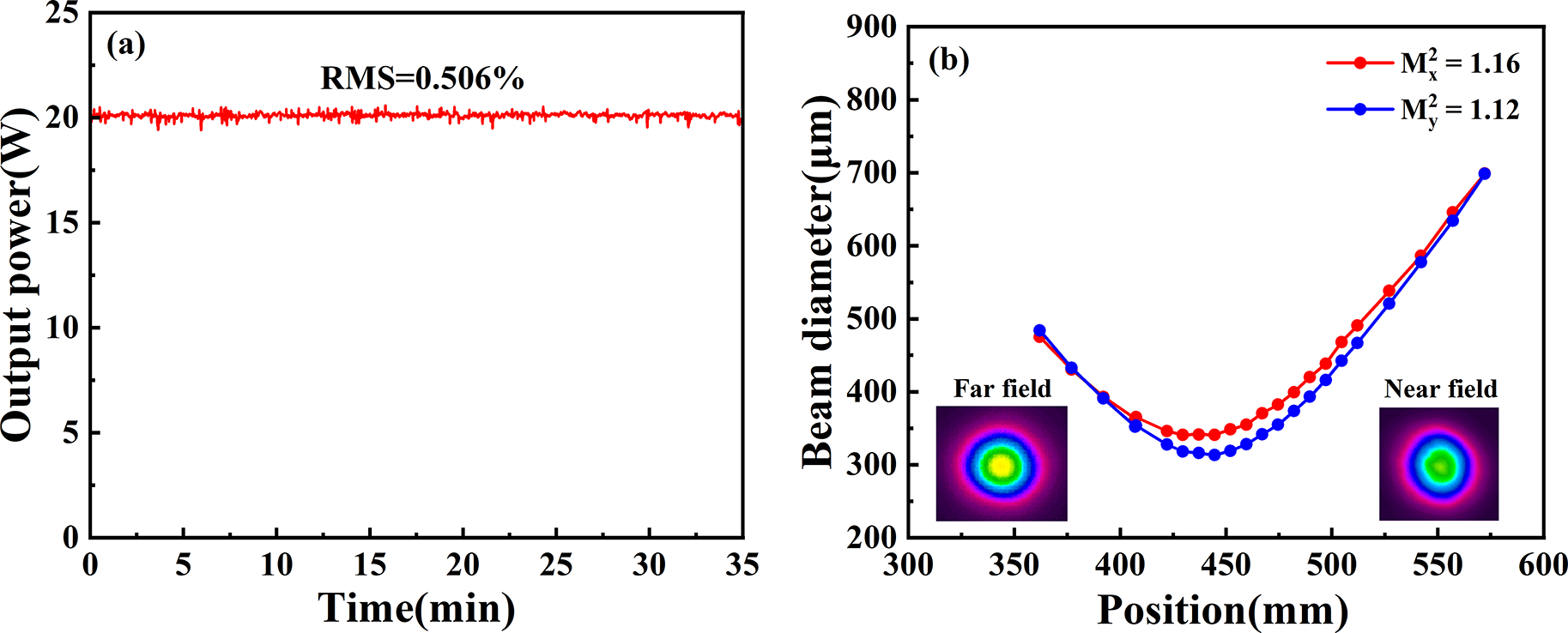
Figure 8 (a) Power stability at an average output power of 20.10 W. (b) M 2 values measured at a repetition rate of 1 kHz, with near-field and far-field beam profiles shown in the inset.
4 Conclusion
In this work, we developed a high-peak-power dual-crystal RA cavity based on Yb:CALGO. By combining a thermally insensitive cavity design with quasi-CW pumping, the RA achieved a maximum pulse energy of 21.01 mJ at a repetition rate of 1 kHz. Under stable operating conditions, after compression, the pulse energy reached 17.6 mJ with a pulse duration of 137 fs, corresponding to a peak power of 0.112 TW. The M 2 values in the two orthogonal directions were 1.16 and 1.12, respectively. The power stability over 30 minutes was measured to be 0.506%. To the best of our knowledge, this represents the highest peak power ever reported from a Yb:CALGO RA. The pulse duration of the RA cavity has not yet reached its FTL due to the dispersion mismatch between the stretcher and compressor. In the next step, we aim to combine multi-pass amplification and post-compression to achieve a peak power of 1 TW.
Acknowledgements
This research was supported by the Strategic Priority Research Program of the Chinese Academy of Sciences (Grant Nos. XDA0380205 and XDB0890101), the National Key Research and Development Program of China (Grant No. 2022YFA1604400), the National Natural Science Foundation of China (Grant Nos. 12388102, 62205351, 61925507, 62075227, 22227901, U21A20138 and 62375273), the Shanghai Rising-Star Program (Grant No. 21QA1410200), the Youth Innovation Promotion Association of the Chinese Academy of Sciences (Grant No. 2020248), the Chinese Academy of Sciences Shanghai Branch (Grant Nos. 22DZ1100300, 22560780100 and 23560750200), the Postdoctoral Fellowship Program of the China Postdoctoral Science Foundation (CPSF) (Grant No. GZC20232817), and the Shanghai Minicipal Science and Technology Major Project.


 Open access