1. Introduction
Ion acceleration via laser-plasma interaction [Reference Macchi, Borghesi and Passoni1] has attracted extensive attention with the rapid development of ultrashort, ultraintense laser technology in recent decades. For its unique characteristics such as high energy and small divergence [Reference Bolaños, Béard and Revet2], it has potential scientific applications in a variety of aspects such as inertial confinement fusion (ICF) [Reference He, Cai and Wu3–Reference Gong, Hao and Li6], tumor therapy [Reference Bulanov, Esirkepov, Khoroshkov, Kuznetsov and Pegoraro7, Reference Schardt8], and proton imaging [Reference Borghesi, Schiavi and Campbell9, Reference Borghesi, Mackinnon and Campbell10]. Several mechanisms for laser-driven ion acceleration have been proposed and observed experimentally over the past decades, including target normal sheath acceleration (TNSA) [Reference Snavely, Key and Hatchett11, Reference Hatchett, Brown and Cowan12], radiation pressure acceleration (RPA) [Reference Liseykina, Borghesi, Macchi and Tuveri13–Reference Esirkepov, Borghesi, Bulanov, Mourou and Tajima15], break-out afterburner (BOA) [Reference Yin, Albright and Hegelich16, Reference Henig, Kiefer and Markey17], magnetic vortex acceleration (MVA) [Reference Nakamura and Mima18, Reference Kuznetsov, Esirkepov, Kamenets and Bulanov19], and collisionless shock acceleration (CSA) [Reference Forslund and Freidberg20–Reference Denavit22]. Among them, the RPA and CSA mechanisms have the potential in generating high-energy and quasimonoenergetic ion beams. However, because of the extreme laser conditions required such as ultrahigh intensity and ultrahigh contrast, the evidence for RPA is scant in experiments. Comparatively, CSA is easier to perform and has been reported recently in experiments [Reference Palmer, Dover and Pogorelsky23, Reference Zhang, Shen and Wang24]. In laser-driven CSA, the laser pulse launches a collisionless electrostatic shock in the plasmas by radiation pressure. As the shock propagates forward, it reflects a portion of the background ions to approximately twice the shock velocity due to the strong electrostatic field associated with the shock front. For ions to be reflected, their initial velocity in the shock frame should satisfy [Reference Fiuza, Stockem and Boella25]
![]() , where ϕ is the potential corresponding to the electrostatic field in the shock front and mi is the mass of the ion. Thus, the energy of reflected ions is strongly dependent on the shock strength. To improve the quality of the CSA, Zhang et al. [Reference Zhang, Cai, Wei, Tian and Zhu26] have proposed to externally apply a strong transverse magnetic field (about 2 ∼ 10 kT) to the plasmas. This field influences the transportation of hot electrons by inhibiting their expansion in the longitudinal direction. As more hot electrons are confined near the shock front region, the shock strength is enhanced due to the increased thermal pressure. Therefore, the energy of accelerated ions is greatly enhanced. However, a uniform and stable external magnetic field of such a high intensity is not easy to generate in experiments. Recent works have shown that the nanostructured targets are capable of generating magnetic fields of over 10 kT in both simulations and experiments [Reference Tian, Cai, Zhang, Zhang, Du and Zhu27–Reference Chatterjee, Singh and Ahmed29]. Besides, the nanostructured targets are much more efficient in laser absorption and hot electron generation compared with planar targets [Reference Zhao, Cao and Cao30–Reference Samsonova, Höfer and Kaymak32]. As more hot electrons are generated and collimated inside the gaps of the nanostructured targets, it has the potential advantages for the subsequent ion acceleration. For example, enhanced target normal sheath acceleration in nanostructured targets has been reported to greatly enhance the quality of the ion beam in both simulations [Reference Yu, Zhao and Jin33–Reference Xie, Cao and Chao35] and experiments [Reference Moreau, Hollinger and Calvi36, Reference Dozières37]. At the same time, with the development of surface microtechnology, many novel targets with nanostructures are realized in experiments, such as subwavelength gratings [Reference Kahaly, Yadav and Wang38], metal nanobrushes [Reference Hollinger, Bargsten and Shlyaptsev39, Reference Khaghani, Lobet and Borm40], and silicon and oxide nanowires [Reference Cristoforetti, Londrillo and Singh41, Reference Black, Leedle, Miao, Niedermayer, Byer and Solgaard42]. With these technological advances, even more complex nanostructured targets could be feasible in the future.
, where ϕ is the potential corresponding to the electrostatic field in the shock front and mi is the mass of the ion. Thus, the energy of reflected ions is strongly dependent on the shock strength. To improve the quality of the CSA, Zhang et al. [Reference Zhang, Cai, Wei, Tian and Zhu26] have proposed to externally apply a strong transverse magnetic field (about 2 ∼ 10 kT) to the plasmas. This field influences the transportation of hot electrons by inhibiting their expansion in the longitudinal direction. As more hot electrons are confined near the shock front region, the shock strength is enhanced due to the increased thermal pressure. Therefore, the energy of accelerated ions is greatly enhanced. However, a uniform and stable external magnetic field of such a high intensity is not easy to generate in experiments. Recent works have shown that the nanostructured targets are capable of generating magnetic fields of over 10 kT in both simulations and experiments [Reference Tian, Cai, Zhang, Zhang, Du and Zhu27–Reference Chatterjee, Singh and Ahmed29]. Besides, the nanostructured targets are much more efficient in laser absorption and hot electron generation compared with planar targets [Reference Zhao, Cao and Cao30–Reference Samsonova, Höfer and Kaymak32]. As more hot electrons are generated and collimated inside the gaps of the nanostructured targets, it has the potential advantages for the subsequent ion acceleration. For example, enhanced target normal sheath acceleration in nanostructured targets has been reported to greatly enhance the quality of the ion beam in both simulations [Reference Yu, Zhao and Jin33–Reference Xie, Cao and Chao35] and experiments [Reference Moreau, Hollinger and Calvi36, Reference Dozières37]. At the same time, with the development of surface microtechnology, many novel targets with nanostructures are realized in experiments, such as subwavelength gratings [Reference Kahaly, Yadav and Wang38], metal nanobrushes [Reference Hollinger, Bargsten and Shlyaptsev39, Reference Khaghani, Lobet and Borm40], and silicon and oxide nanowires [Reference Cristoforetti, Londrillo and Singh41, Reference Black, Leedle, Miao, Niedermayer, Byer and Solgaard42]. With these technological advances, even more complex nanostructured targets could be feasible in the future.
In this study, we investigate the scheme for enhancing CSA with a solid nanolayered target embedding in the near-critical plasmas. The fabrication of such a target in the experiment could possibly be realized by inserting the nanolayers in a porous foam target [Reference Prencipe, Sgattoni and Dellasega43]. An intense laser drives the near-critical plasma filled in the gaps of the nanolayers to form a stable collisionless shock as in the regular CSA. Due to the nanolayers, electrons of high density within the mare are heated and dragged out by lasers, giving a contribution to the generation of more hot electrons. Also, the current generated along the surface of the nanolayers induces a strong transverse magnetic field in the near-critical plasma in the gaps. This field acts like a stable external field, inhibiting the longitudinal propagation of hot electrons and focusing them near the shock front. Both effects contribute to the strength of the collisionless shock, leading to an enhancement of the CSA. The effects of the nanolayers on the CSA are studied via two-dimensional particle-in-cell (PIC) simulations, and cases of near-critical plasmas with or without nanolayers are carried out and compared to demonstrate the enhancement of CSA. Simulation results verify the enhancement of proton acceleration, and both the peak energy and cutoff energy for accelerated protons are increased in the case with nanolayers.
This paper is organized as follows. In Section 2, the target setup and simulation parameters are presented. In Section 3, the dynamics and enhancement of CSA are analyzed in detail. In addition, the effect of nanolayers width on CSA is discussed. Section 4 is the conclusion and summary.
2. Simulation Setup
To study the effect of the nanolayered target (NLT) on CSA, two-dimensional simulations are carried out with 2D3V PIC codes EPOCH [Reference Arber, Bennett and Brady44]. In the simulation, a circularly polarized laser pulse with wavelength λ0 = 1 μm propagating in the x-direction from the left boundary of the simulation box is incident normally on the target [Reference Zhang, Shen and Wang24]. Its transverse profile is Gaussian, i.e.,
![]() , with a focal spot radius of r 0 = 15 μm and a peak intensity I 0 = 9.8 × 10¹⁹ W/cm2, corresponding to a normalized amplitude a 0 = 6 for the circularly polarized laser. The temporal profile is flat-topped with duration τ = 150T 0, where T 0 = 3.3 fs is the laser period. For simplicity of analyzing, the NLT is modeled by an array of thin plasma layers with spacing embedded in the homogeneous near-critical H+ plasma with a density of 8 ncr, where ncr = 1.1 × 1021cm−3 is the critical density. The nanolayers are assumed to be preionized Au50+ plasma with an electron density of 50 ncr, and they are set immobile in the simulations. Considering the conversion efficiency from laser to hot electrons, a subwavelength nanolayered target is used [Reference Cao, Gu and Zhao45]. Its dimensions are as follows: layer width d 1 = 0.4 μm, length l 1 = 30 μm, and the distance between the centers of two neighboring layers d 2 = 5 μm. The size of the simulation box is
, with a focal spot radius of r 0 = 15 μm and a peak intensity I 0 = 9.8 × 10¹⁹ W/cm2, corresponding to a normalized amplitude a 0 = 6 for the circularly polarized laser. The temporal profile is flat-topped with duration τ = 150T 0, where T 0 = 3.3 fs is the laser period. For simplicity of analyzing, the NLT is modeled by an array of thin plasma layers with spacing embedded in the homogeneous near-critical H+ plasma with a density of 8 ncr, where ncr = 1.1 × 1021cm−3 is the critical density. The nanolayers are assumed to be preionized Au50+ plasma with an electron density of 50 ncr, and they are set immobile in the simulations. Considering the conversion efficiency from laser to hot electrons, a subwavelength nanolayered target is used [Reference Cao, Gu and Zhao45]. Its dimensions are as follows: layer width d 1 = 0.4 μm, length l 1 = 30 μm, and the distance between the centers of two neighboring layers d 2 = 5 μm. The size of the simulation box is
![]() with 2000 × 1500 grid cells and a time step τ = 0.01T 0, and each cell contains 40 particles. Periodic boundary conditions are used in the transverse direction and the nanolayered target is placed in the region of
with 2000 × 1500 grid cells and a time step τ = 0.01T 0, and each cell contains 40 particles. Periodic boundary conditions are used in the transverse direction and the nanolayered target is placed in the region of
![]() . Considering that there might be anomalous fields near the boundary, we only take the region of
. Considering that there might be anomalous fields near the boundary, we only take the region of
![]() into analysis. For comparison, the case of a planar target (PT) without nanolayers is also considered, where the same laser and plasma parameters are used. To illustrate, the configurations of both targets are sketched in Figure 1. It is worth noticing that our scheme is different from the scheme proposed by He et al. [Reference He, Qiao and Shen46], in which the near-critical plasmas are confined by a thick Au50+ tube. The tube confines the transverse expansion of the hot electrons via the induced electric field. However, in our cases, the incident laser has a large focal spot radius and the transverse expansion is negligible.
into analysis. For comparison, the case of a planar target (PT) without nanolayers is also considered, where the same laser and plasma parameters are used. To illustrate, the configurations of both targets are sketched in Figure 1. It is worth noticing that our scheme is different from the scheme proposed by He et al. [Reference He, Qiao and Shen46], in which the near-critical plasmas are confined by a thick Au50+ tube. The tube confines the transverse expansion of the hot electrons via the induced electric field. However, in our cases, the incident laser has a large focal spot radius and the transverse expansion is negligible.

Figure 1: Target configurations of (a) the NLT and (b) the PT. The NLT consists of near-critical hydrogen plasmas and embedding preionized Au50+ nanolayers.
3. Enhancement of the Laser-Driven CSA
In the laser-driven CSA regime, due to the strong radiation pressure of the incident laser exerted on plasmas, electrons and ions are piled up through the hole-boring effect, forming a density spike moving forward along the longitudinal direction. The laser pulse acts like a piston, pushing the disturbed plasma spike to flow into the undisturbed upstream region. The hole-boring velocity can be estimated [Reference Macchi, Cattani, Liseykina and Cornolti47] as
![]() , where c is the light speed in vacuum, ni is the density of the ion, I is the intensity of the incident laser, and mi is the mass of the ion.
, where c is the light speed in vacuum, ni is the density of the ion, I is the intensity of the incident laser, and mi is the mass of the ion.
For the parameters in our cases, the hole-boring velocity is
![]() Figure 2 shows the proton density distributions at a different time for the PT (Figures 2(a) and 2(b)) and the NLT (Figures 2(c) and 2(d)). Density spikes of over 30 ncr can be observed in both cases and they are drifting to the lower density upstream region. The density ratio of disturbed downstream density spike to the undisturbed upstream plasmas can be obtained from Figure 2, being approximately
Figure 2 shows the proton density distributions at a different time for the PT (Figures 2(a) and 2(b)) and the NLT (Figures 2(c) and 2(d)). Density spikes of over 30 ncr can be observed in both cases and they are drifting to the lower density upstream region. The density ratio of disturbed downstream density spike to the undisturbed upstream plasmas can be obtained from Figure 2, being approximately
![]() . Furthermore, a significant number of hot electrons are generated to heat the plasma volume by the laser pulse. Figure 3(a) presents the electron energy spectrum at t = 100 T 0. There are hot electrons ranging from 10 MeV to 30 MeV and more hot electrons are generated in the NLT due to the nanolayers. By fitting the curves with Maxwellian distribution, the slope of the fitted line gives the hot electron temperature T hot ≈ 3.7 MeV in both cases, and ion acoustic speed is estimated as
. Furthermore, a significant number of hot electrons are generated to heat the plasma volume by the laser pulse. Figure 3(a) presents the electron energy spectrum at t = 100 T 0. There are hot electrons ranging from 10 MeV to 30 MeV and more hot electrons are generated in the NLT due to the nanolayers. By fitting the curves with Maxwellian distribution, the slope of the fitted line gives the hot electron temperature T hot ≈ 3.7 MeV in both cases, and ion acoustic speed is estimated as
![]() . Figures 3(b) and 3(c) show the hot electrons from the near-critical plasmas and the nanolayers, respectively. It can be seen that electrons from the nanolayers also contribute to the hot electron generation near the shock front. In Figure 4, the snapshots of longitudinal momentum phase space of protons at t = 100 T 0 (Figures 4(a) and 4(b)) and t = 150 T 0 (Figures 4(c) and 4(d)) are presented. The phase space distributions show a significant structure of a typical collisionless shock [Reference Sarri, Dieckmann, Kourakis and Borghesi48]. As labeled in Figure 4(a), the shock velocity is estimated as vsh = 0.08 c, with a corresponding Mach number Msh ≈ 1.4, which is approximately the critical Mach number for ion reflection [Reference Fiuza, Stockem and Boella25] Mcr ≈ 1.4. There are a bunch of reflected protons in the upstream region, and their velocity is approximately twice the shock velocity. Both cases at different times show similar phase space structures and reflected protons. It is worth noticing that the shock velocity and the momentum of reflected protons are significantly increased in the NLT.
. Figures 3(b) and 3(c) show the hot electrons from the near-critical plasmas and the nanolayers, respectively. It can be seen that electrons from the nanolayers also contribute to the hot electron generation near the shock front. In Figure 4, the snapshots of longitudinal momentum phase space of protons at t = 100 T 0 (Figures 4(a) and 4(b)) and t = 150 T 0 (Figures 4(c) and 4(d)) are presented. The phase space distributions show a significant structure of a typical collisionless shock [Reference Sarri, Dieckmann, Kourakis and Borghesi48]. As labeled in Figure 4(a), the shock velocity is estimated as vsh = 0.08 c, with a corresponding Mach number Msh ≈ 1.4, which is approximately the critical Mach number for ion reflection [Reference Fiuza, Stockem and Boella25] Mcr ≈ 1.4. There are a bunch of reflected protons in the upstream region, and their velocity is approximately twice the shock velocity. Both cases at different times show similar phase space structures and reflected protons. It is worth noticing that the shock velocity and the momentum of reflected protons are significantly increased in the NLT.
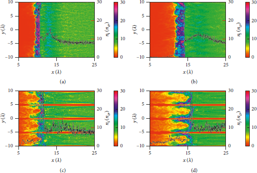
Figure 2: Snapshots and longitudinal density profiles (black dashed lines) of the proton densities at t = 100 T 0 for (a) the PT and (c) the NLT and at t = 150 T 0 for (b) the PT and (d) the NLT. The density peak is approximately 30 ncr and the density of undisturbed plasmas in the upstream region is 8 ncr.
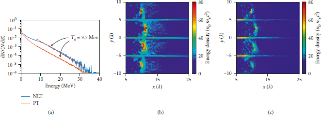
Figure 3: (a) Energy spectrum of electrons at t = 100 T 0 for the PT (red line) and the NLT (blue line). The hot electron number for the PT is more than that for the NLT, but the temperature for both cases is almost the same as Te ≈ 3.7 MeV. Energy densities of the two different electrons from the near-critical plasmas (b) and from the nanolayers (c) at t = 100 T 0.
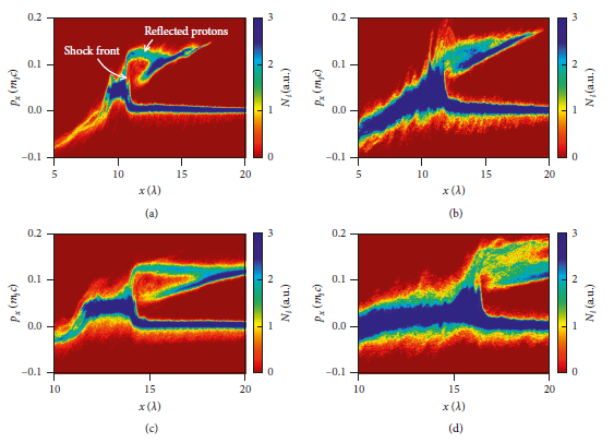
Figure 4: Phase space (px − x) of protons are plotted for the PT (a) and the NLT (b) at t = 100 T 0 and for the PT (c) and the NLT (d) at t = 150 T 0.
To obtain the precise shock velocity, the time evolution of the longitudinal electrostatic field is presented in Figure 5 for the PT (Figure 5(a)) and the NLT (Figure 5(b)), respectively. It can be observed that collisionless shocks are launched at approximately t = 50 T 0 in both cases. The black dashed and dotted lines mark the positions of the peak value. The shock propagates forward at a stable speed after its formation. The reciprocal of the slope of the line gives the velocity of the shock. For the PT, the shock velocity can be estimated from Figure 5(a) as vsh = 0.079 c, while for the NLT in Figure 5(b), the shock velocity is vsh = 0.091 c, as much as 25% higher compared to the former. It is worth noticing that, in both cases, as shown in Figures 5(a) and 5(b), there is an obvious turn of the electrostatic field peak at approximately 50 T 0, marking the formation of the shock, because at the early stage, hole-boring effects dominate and the laser pushes the whole plasma forward. As a result, plasma is piled up and drifts at hole-boring velocity. Once the shock launches, it has a velocity larger than the hole-boring velocity, which can be clearly seen from the slope of the black and green lines. At t < 50 T 0 region, the hole-boring velocity is estimated to be vHB ≈ 0.06c, approximately the value obtained by the theory. To better illustrate the difference between the two cases, the black dashed line from Figure 5(a) is translated to the same position in Figure 5(b), showing a clear divergence of shock velocity between the PT and the NLT. Figure 5(c) shows the energy spectrum of protons accelerated by the collisionless shock wave in the upstream region at t = 150 T 0. Both PT and NLT feature a quasimonoenergetic energy spectrum. In addition, the peak energy and cutoff energy of accelerated protons are both enhanced in the NLT compared to the PT. The peak energy increases from 6.9 MeV to 9.1 MeV by 30%, and the cutoff energy increases as much as 60% from 12.2 MeV to 20.0 MeV. The increase of shock velocity and proton energy indicates a much stronger shock in the NLT.
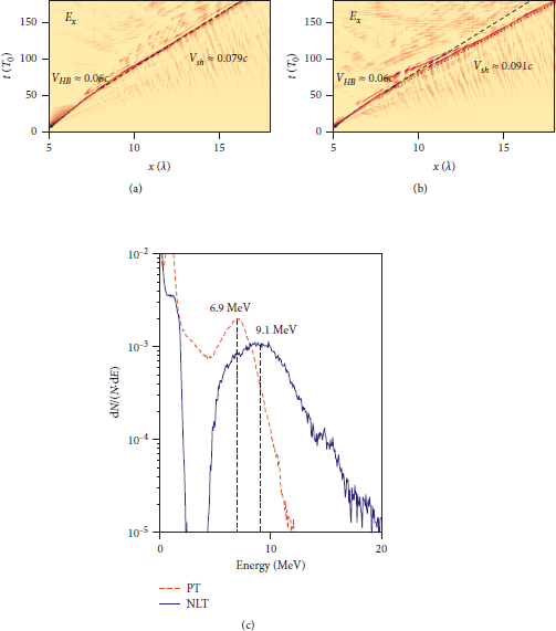
Figure 5: Time evolution of longitudinal electrostatic field for (a) the PT and (b) the NLT, where the black dashed line marks the shock front for the PT and the dotted line for the NLT. The hole-boring mechanism in the early stage is also marked as green dashed line, and the hole-boring velocity vHB ≈ 0.06 c. (c) Energy spectrum of accelerated protons in the upstream region at t = 150 T 0.
The enhancement of the shock strength can be explained by the generation and transportation of hot electrons from nanolayers. As can be seen from the slope of the dashed lines in Figure 3, the temperature of hot electrons is almost the same in both cases. But with solid nanolayers, the number of hot electrons is increased due to the laser-nanolayer interaction. Besides, the current in the nanolayers generates a strong and inhomogeneous transverse magnetic field Bz, as shown in Figures 6(a) and 6(b), for the PT and the NLT, respectively, where Bz is normalized by
![]() . The induced Bz inhibits the propagation of the hot electrons in the x-direction. Furthermore, due to the nonhomogeneity of Bz in the y-direction, it exerts a magnetic pressure of
. The induced Bz inhibits the propagation of the hot electrons in the x-direction. Furthermore, due to the nonhomogeneity of Bz in the y-direction, it exerts a magnetic pressure of
![]() on the hot electrons, expelling them from the region near the nanolayers and pushing them towards the center of the gap, leading to a further accumulation of the hot electrons. The accumulation of hot electrons results in an increased thermal pressure in the shock front region, which can be expressed as
on the hot electrons, expelling them from the region near the nanolayers and pushing them towards the center of the gap, leading to a further accumulation of the hot electrons. The accumulation of hot electrons results in an increased thermal pressure in the shock front region, which can be expressed as
![]() , where nh and Th are the density and temperature of hot electrons, respectively. This thermal pressure leads to the enhancement of shock strength by increasing the electric field
, where nh and Th are the density and temperature of hot electrons, respectively. This thermal pressure leads to the enhancement of shock strength by increasing the electric field
![]() , where Ex is the electric field associated with the shock front. To illustrate, Figures 6(c) and 6(d) show the energy density distribution of hot electrons. It can be seen that electrons are focused and more energetic in the NLT. However, in the PT, they are scattered and distributed in a wider region, leading to a weaker shock. To further illustrate, Ex associated with the shock front at t = 100T 0 and t = 150T 0 is exhibited in Figures 7(a), 7(b), 7(d), and 7(e), normalized by
, where Ex is the electric field associated with the shock front. To illustrate, Figures 6(c) and 6(d) show the energy density distribution of hot electrons. It can be seen that electrons are focused and more energetic in the NLT. However, in the PT, they are scattered and distributed in a wider region, leading to a weaker shock. To further illustrate, Ex associated with the shock front at t = 100T 0 and t = 150T 0 is exhibited in Figures 7(a), 7(b), 7(d), and 7(e), normalized by
![]() . Figures 7(c) and 7(f) compare Ex by averaging them over the y-direction. We can see that the peak value of Ex is increased as much as 30% compared to that in the PT at different moments and that the shock in the NLT propagates faster than that in the PT, indicating a stronger shock.
. Figures 7(c) and 7(f) compare Ex by averaging them over the y-direction. We can see that the peak value of Ex is increased as much as 30% compared to that in the PT at different moments and that the shock in the NLT propagates faster than that in the PT, indicating a stronger shock.
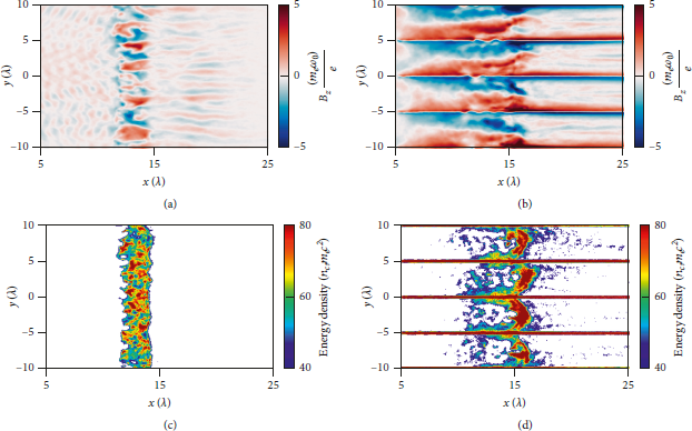
Figure 6: The transverse magnetic fields Bz and the energy density distributions of hot electrons at t = 150T 0 for (a, c) the PT and (b, d) the NLT. Bz is normalized by
![]() , and the energy density is normalized by
, and the energy density is normalized by
![]() . The average magnetic field near the shock front is about 10 kT. These hot electrons have a typical gyro-radius of
. The average magnetic field near the shock front is about 10 kT. These hot electrons have a typical gyro-radius of
![]() .
.
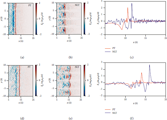
Figure 7: Plots of Ex distribution at t = 100T 0 (a, b) and t = 150 T 0 (d, e) for the PT and the NLT, respectively. Ex averaged over the transverse direction at (c) t = 100 T 0 and (f) t = 150 T 0.
Furthermore, nanolayered targets with different gap widths are investigated to find out a possibly optimal parameter. NLT with corresponding d 2 = 3, 5, 7, 10 μm and PT are separately applied in the simulations for comparison. Figure 8 shows the energy spectra of accelerated protons in different cases. As we can see, in all cases of NLT, the peak energy and cutoff energy are increased compared to the PT. As the gap width decreases from 10 μm to 5 μm, both the peak energy and cutoff energy increase, while the energy spectra of the protons broaden and become quasimonoenergetic. However, as the gap width further decreases to 3 μm, the peak energy remains the same. But the cutoff energy and the proportion of protons with high energy decreases, meaning decreased conversion efficiency from laser to accelerated protons. While the nanolayers contribute to the hot electron generation and induce the magnetic field, they can also reflect the incident laser. As the gap width decreases, more nanolayers interact with the incident laser, and the proportion of reflected laser will increase. Besides, the hot electrons not only enhance the shock strength but also heat the plasmas in the upstream region. When the gap width decreases, more hot electrons are generated, meaning an increased ion acoustic speed, which results in a lower Mach number and a decrease in the efficiency of the CSA. Thus, the optimal gap width d 2 = 5 μm is achieved for the current NLT configuration.
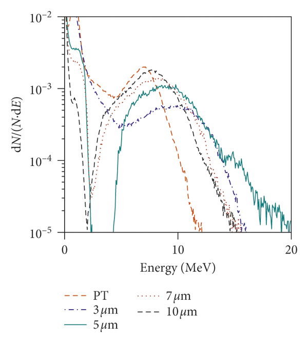
Figure 8: The proton energy spectrum for the PT and the NLT with different widths at t = 150T 0.
4. Summary
In this paper, the effects of nanolayered targets on the laser-driven collisionless shock acceleration are investigated via 2D3V PIC simulations. To conclude, a stable and strong collisionless shock can be formed in the near-critical plasma embedding with a nanolayered target. More hot electrons are generated due to the interaction of the nanolayers and the incident laser. Besides, the current generated along the nanolayers induces a strong transverse magnetic field in the near-critical plasma surrounding nanolayers, which helps to inhibit the longitudinal propagation of hot electrons and accumulate them near the shock front. Compared with the planar target case, shock velocity increased from 0.079c to 0.091c, and the electric field associated with the shock front is also reinforced. Consequently, both peak energy and cutoff energy of the accelerated protons in the upstream region are increased by as much as 30%. Furthermore, we investigated the effect of the gap width. As the gap width decreases, the peak energy and cutoff energy increase. However, when the gap is too narrow, the quasimonoenergetic feature of CSA is impaired, and the proportion of high-energy protons declines. Our simulations provide a potential scheme for the enhancement of the CSA in experiments while careful and detailed investigations concerning the laser and target parameters for a more realistic setup should be considered in future work.
Data Availability
The data that support the findings of this study are available from the corresponding author upon reasonable request.
Conflicts of Interest
The authors declare that they have no conflicts of interest.
Acknowledgments
This work was supported by the National Natural Science Foundation of China (Grant nos. 11875091 and 11975059), the National Key Research and Development Program of China (Grant no. 2016YFA0401100), and the Science and Technology on Plasma Physics Laboratory at CAEP (Grant no. JCKYS2019212012).


