


1. Introduction
The defining feature of the stellarator approach to magnetic fusion is that the plasma performance is determined by externally applied, judiciously chosen three-dimensional (3-D) magnetic fields (Helander Reference Helander2014; Boozer Reference Boozer2015). While the 3-D nature of the configurations provides complexity to design, considerable progress has been made in the past several decades in the areas of theoretical modeling, computational capability and the introduction of the concept of the optimized stellarator (Nührenberg & Zille Reference Nührenberg and Zille1986, Reference Nührenberg and Zille1988; Nührenberg Reference Nührenberg2010) to overcome these challenges. Indeed, the world’s fleet of stellarator experiments have definitively validated the optimized stellarator approach to improved magnetic confinement (Canik et al. Reference Canik, Anderson, Anderson, Likin, Talmadge and Zhai2007; Dinklage et al. Reference Dinklage2018; Beidler et al. Reference Beidler2021) and provide us with considerable confidence that desired properties of a stellarator fusion reactor can be designed into the configuration. With this progress in plasma science, bolstered by advances in superconducting magnet technology (Riva et al. Reference Riva2023), we can now credibly pursue a fusion energy pilot plant using the stellarator concept. In this and the succeeding set of journal articles, we lay out the physics basis for realizing stellarator fusion. Fundamentally, the present study produces an integrated stellarator design that demonstrates no ‘show-stopping’ physics that cannot be overcome with present day optimization approaches.
For this study, we utilize empirical results informed by decades of stellarator experimental work and state-of-the-art theoretical and computational physics tools to design and assess the performance of a potential stellarator fusion pilot plant (FPP). During the course of this study, the Type One Energy optimization group assembled a large database of stellarator configurations. In creating this database, a broad array of design space was considered with variations in field period, aspect ratio, rotational transform, desired physics properties, etc. using a variety of optimization techniques and optimization weightings in the algorithms used to generate new configurations. These configurations were assessed using a collection of theoretical and numerical tools ranging from metrics provided by analytic theory to high-fidelity computation. From this dataset, we selected a single configuration (the Infinity Two FPP baseline plasma physics design) to undergo a comprehensive evaluation of its physics properties consistent with a set of buildable coils, divertor solution and required shielding and blanket requirements with tritium breeding ratio greater than unity. Moreover, a steady-state deuterium-tritium (DT) fusion scenario is developed consistent with limitations imposed by neutron wall loading and energetic particle-induced hot spots. For nearly all aspects of the physics assessments, state-of-the-art computational technology is employed. An important aspect of this study is the direct inclusion of nonlinear gyrokinetic evaluation as part of self-consistent transport modeling of the configuration using the T3D-GX code suite (Barnes et al. Reference Barnes, Abel, Dorland, Görler, Hammett and Jenko2010; Mandell et al. Reference Mandell, Dorland, Abel, Gaur, Kim, Martin and Qian2024), enabling first-principles predictions of the plasma performance and fusion gain. The goal of this work is to demonstrate that the stellarator configuration we have designed meets all of the needs of a stellarator pilot plant.
The configuration selected for this study is an aspect ratio $A = 10$
stellarator in which the number of field periods is
$A = 10$
stellarator in which the number of field periods is $N = 4$
. In many ways, Infinity Two resembles the Wendelstein 7-X (W7-X) configuration (Dinklage et al. Reference Dinklage2018; Beidler et al. Reference Beidler2021) as the concept of quasi-isodynamicity is used as the approach to minimize neoclassical transport. Quasi-isodynamic (QI) stellarators are characterized by having all collisionless particle orbits confined to the plasma and the magnetic-field-strength contours closing poloidally (Helander Reference Helander2014). However, our configuration attempts to improve the W7-X design in all topical areas with particular emphasis on the confinement of energetic ions and turbulent transport. The configuration here is also reminiscent of
$N = 4$
. In many ways, Infinity Two resembles the Wendelstein 7-X (W7-X) configuration (Dinklage et al. Reference Dinklage2018; Beidler et al. Reference Beidler2021) as the concept of quasi-isodynamicity is used as the approach to minimize neoclassical transport. Quasi-isodynamic (QI) stellarators are characterized by having all collisionless particle orbits confined to the plasma and the magnetic-field-strength contours closing poloidally (Helander Reference Helander2014). However, our configuration attempts to improve the W7-X design in all topical areas with particular emphasis on the confinement of energetic ions and turbulent transport. The configuration here is also reminiscent of $N=4$
,
$N=4$
, $A=10$
QI configurations published recently by Sánchez et al. (Reference Sánchez, Velasco, Calvo and Mulas2023) and Goodman et al. (Reference Goodman, Xanthopoulos, Plunk, Smith, Nührenberg, Beidler, Henneberg, Roberg-Clark, Drevlak and Helander2024). The approach used here relies on a high magnetic field with a volume-averaged magnetic field
$A=10$
QI configurations published recently by Sánchez et al. (Reference Sánchez, Velasco, Calvo and Mulas2023) and Goodman et al. (Reference Goodman, Xanthopoulos, Plunk, Smith, Nührenberg, Beidler, Henneberg, Roberg-Clark, Drevlak and Helander2024). The approach used here relies on a high magnetic field with a volume-averaged magnetic field $\langle B \rangle = 9$
T. A set of magnetic coils and a corresponding free-boundary magnetohydrodynamic (MHD) equilibrium is obtained consistent with the desired physics properties. Moreover, engineering constraints on the coil design are imposed resulting in the configuration having sufficiently large plasma-to-coil and coil-to-coil distances. With a high magnetic field approach, a stellarator reactor can be realized at somewhat more compact sizes and/or less aggressive physics than seen in prior stellarator reactor studies (Beidler et al. Reference Beidler2001; Sagara et al. Reference Sagara2006; Najmabadi et al. Reference Najmabadi2008; Menard et al. Reference Menard2011; Warmer et al. Reference Warmer2017; Alonso et al. Reference Alonso, Calvo, Carralero, Velasco, Garc-a-Regaña, Palermo and Rapisarda2022). For this work, an
$\langle B \rangle = 9$
T. A set of magnetic coils and a corresponding free-boundary magnetohydrodynamic (MHD) equilibrium is obtained consistent with the desired physics properties. Moreover, engineering constraints on the coil design are imposed resulting in the configuration having sufficiently large plasma-to-coil and coil-to-coil distances. With a high magnetic field approach, a stellarator reactor can be realized at somewhat more compact sizes and/or less aggressive physics than seen in prior stellarator reactor studies (Beidler et al. Reference Beidler2001; Sagara et al. Reference Sagara2006; Najmabadi et al. Reference Najmabadi2008; Menard et al. Reference Menard2011; Warmer et al. Reference Warmer2017; Alonso et al. Reference Alonso, Calvo, Carralero, Velasco, Garc-a-Regaña, Palermo and Rapisarda2022). For this work, an $800$
MW DT high fusion gain
$800$
MW DT high fusion gain $(Q = 40)$
fusion source is designed with minor and major radii
$(Q = 40)$
fusion source is designed with minor and major radii $a = 1.25$
m,
$a = 1.25$
m, $R = 12.5$
m and baseline volume-averaged plasma density
$R = 12.5$
m and baseline volume-averaged plasma density $n_e \approx 2 \times 10^{20}$
m
$n_e \approx 2 \times 10^{20}$
m $^{-3}$
. Additionally, high-fidelity transport analysis shows ignited (
$^{-3}$
. Additionally, high-fidelity transport analysis shows ignited ( $Q=\infty$
) DT fusion operation with
$Q=\infty$
) DT fusion operation with $P_{{fusion}} \approx 1.5$
GW can be attained at higher plasma density at the cost of higher neutron wall loading, a more challenging exhaust problem and higher energetic particle-induced hot spots. We did not endeavor to perform a comprehensive engineering optimization to provide a best solution to this scenario, however, it is encouraging that the plasma physics enables more aggressive reactor outputs. Indeed, the configuration presented here is one of many stellarator designs produced in the Type One Energy study that likely has reactor realizability. Certainly, in the ensuing years, as optimization techniques continue to improve and plasma science advances, more attractive stellarator reactor designs will be produced. Indeed, a number of very favorable configurations from the Type One Energy database with simultaneously lower aspect ratio, reduced turbulent transport, reduced alpha-particle losses and better coil buildability than Infinity Two are currently awaiting the comprehensive analysis similar to that carried out in this study. The goal of this work is to present a configuration that will succeed as a fusion pilot plant based on the established physics basis of the stellarator community.
$P_{{fusion}} \approx 1.5$
GW can be attained at higher plasma density at the cost of higher neutron wall loading, a more challenging exhaust problem and higher energetic particle-induced hot spots. We did not endeavor to perform a comprehensive engineering optimization to provide a best solution to this scenario, however, it is encouraging that the plasma physics enables more aggressive reactor outputs. Indeed, the configuration presented here is one of many stellarator designs produced in the Type One Energy study that likely has reactor realizability. Certainly, in the ensuing years, as optimization techniques continue to improve and plasma science advances, more attractive stellarator reactor designs will be produced. Indeed, a number of very favorable configurations from the Type One Energy database with simultaneously lower aspect ratio, reduced turbulent transport, reduced alpha-particle losses and better coil buildability than Infinity Two are currently awaiting the comprehensive analysis similar to that carried out in this study. The goal of this work is to present a configuration that will succeed as a fusion pilot plant based on the established physics basis of the stellarator community.
In the following section, we make the case for the high-field stellarator as a realizable fusion pilot plant. In § 3, a description of the optimization scheme employed in these studies is discussed. The basic configuration details of the stellarator are provided in § 4. An assessment of the plasma confinement properties is provided in § 5. Necessarily, the plasma confinement section will provide a high level summary of the results, with a more comprehensive discussion of the MHD equilibrium and stability properties, energetic particle physics and transport modeling provided in the accompanying set of papers from Carbajal et al. (Reference Carbajal2025), Guttenfelder et al. (Reference Guttenfelder2025), and Schmitt et al. (Reference Schmitt2025) respectively. A consistency of the physics design with a divertor, shielding and blanket solution is given in § 6. A more complete discussion of these topics are provided in accompanying papers by Bader et al. (Reference Bader2025) and Clark et al. (Reference Clark2025). A summary discussion is provided in § 7.
2. The case for the high-field stellarator
The stellarator has a number of intrinsic advantages with regard to its applicability as a fusion reactor. The stellarator is naturally steady state and has minimal recirculating power needs. Generally, stellarators do not suffer from disruptions or the associated generation of a damaging runaway electron population. With robust magnetic surfaces in vacuum, plasma start-up is easy with highly reproducible discharges. These features translate to the stellarator having high reliability as a fusion power plant.
There has been considerable success in the stellarator experimental program where the Helically Symmetric Experiment (HSX) (Anderson et al. Reference Anderson1995), W7-X (Klinger et al. Reference Klinger2017) and to a different degree the Large Helical Device (LHD) (Motojima et al. Reference Motojima2003) and Wendelstein 7-AS (Wagner et al. Reference Wagner2005), definitively demonstrated the virtue of optimization. A major result from the HSX and W7-X programs is that the poor neoclassical transport of conventional stellarators can be eliminated with optimization (Canik et al. Reference Canik, Anderson, Anderson, Likin, Talmadge and Zhai2007; Beidler et al. Reference Beidler2021). Moreover, W7-X results also indicate that impurity accumulation can be avoided, even in the ion-root regime of neoclassical transport, as typically turbulent transport plays a more important role in impurity transport when neoclassical optimization is operative (Langenberg et al. Reference Langenberg2020). Stellarators generally show robustness to MHD instability with confinement degradation, rather than disruptive behavior, as the nonlinear consequence of violating stability boundaries (Weller et al. Reference Weller2009). Importantly, W7-X has also demonstrated routine stable radiative divertor solutions with an island divertor (Pedersen et al. Reference Pedersen2019).
One important lesson from the experimental results is that plasma theory can be trusted to improve the stellarator. The theoretical concepts of quasi-symmetry (QS) (Nührenberg & Zille, Reference Nührenberg and Zille1988) (whereby a continuous symmetry in the $|B|$
spectrum in Boozer coordinates (Boozer Reference Boozer1980) exists) and quasi-isodynamicity (QI) (Cary & Shasharinia Reference Cary and Shasharinia1997) have emerged as defining characteristics of neoclassically optimized stellarators. In recent years, substantial improvements in understanding the 3-D plasma physics of high temperature stellarators have been realized through the development of computational tools in a various topical areas, including turbulent transport, energetic particle confinement, extended MHD, edge/divertor modeling, etc. (Hegna et al. Reference Hegna2022). To a large extent, these tools are being validated on existing stellarator (and tokamak) experiments. Additionally, there has been considerable efforts focused on simplifying coil design (Landreman Reference Landreman2017; Zhu et al. Reference Zhu, Hudson, Song and Wan2018a
,
Reference Zhu, Hudson, Song and Wanb
; Kappel et al. Reference Kappel, Landreman and Malhotra2024). With significant new understanding emerging as a consequence of improvements to stellarator theory, the time is right to realize these advances in new stellarator designs.
$|B|$
spectrum in Boozer coordinates (Boozer Reference Boozer1980) exists) and quasi-isodynamicity (QI) (Cary & Shasharinia Reference Cary and Shasharinia1997) have emerged as defining characteristics of neoclassically optimized stellarators. In recent years, substantial improvements in understanding the 3-D plasma physics of high temperature stellarators have been realized through the development of computational tools in a various topical areas, including turbulent transport, energetic particle confinement, extended MHD, edge/divertor modeling, etc. (Hegna et al. Reference Hegna2022). To a large extent, these tools are being validated on existing stellarator (and tokamak) experiments. Additionally, there has been considerable efforts focused on simplifying coil design (Landreman Reference Landreman2017; Zhu et al. Reference Zhu, Hudson, Song and Wan2018a
,
Reference Zhu, Hudson, Song and Wanb
; Kappel et al. Reference Kappel, Landreman and Malhotra2024). With significant new understanding emerging as a consequence of improvements to stellarator theory, the time is right to realize these advances in new stellarator designs.
There are a number of advantages to the high-field stellarator approach to fusion. In part, these are tied to the ability to run at high density. Empirically, the Sudo density (Sudo et al. Reference Sudo, Takeiri, Zushi, Sano, Itoh, Kondo and Iiyoshi1990) defined by
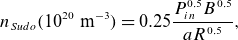 \begin{equation} n_{{Sudo}} (10^{20}\ \textrm{m}^{-3}) = 0.25 \frac {P^{0.5}_{in} B^{0.5}}{a R^{0.5}}, \end{equation}
indicates the operational boundary on the line average plasma density (in units of $10^{20}$
m
$10^{20}$
m $^{-3}$
) improves with field strength. Here,
$^{-3}$
) improves with field strength. Here, $P_{in}$
denotes the absorbed power (MW),
$P_{in}$
denotes the absorbed power (MW), $B$
is the magnetic field strength on the magnetic axis (T),
$B$
is the magnetic field strength on the magnetic axis (T), $a$
is the average minor radius (m) and
$a$
is the average minor radius (m) and $R$
is the major radius (m). The Sudo limit is primarily set by radiation physics and can, in practice, be exceeded with pellet fueling with the edge density determining operational boundaries. Nevertheless, the Sudo estimate still enables multi-
$R$
is the major radius (m). The Sudo limit is primarily set by radiation physics and can, in practice, be exceeded with pellet fueling with the edge density determining operational boundaries. Nevertheless, the Sudo estimate still enables multi- $10^{20}$
m
$10^{20}$
m $^{-3}$
plasma density operation at
$^{-3}$
plasma density operation at $B \sim 9$
T. Correspondingly, high plasma confinement times are allowed at simultaneous high densities and field strengths as indicated by the ISS04 confinement scaling law (Yamada et al. Reference Yamada2005)
$B \sim 9$
T. Correspondingly, high plasma confinement times are allowed at simultaneous high densities and field strengths as indicated by the ISS04 confinement scaling law (Yamada et al. Reference Yamada2005)
 \begin{equation} \tau ^{ISS04}_E = 0.465 a^{2.28} R^{0.64} P^{-0.61}_{in} n^{0.54}_e B^{0.84} {{\iota\kern-1pt\!\mbox{-}\kern0.5pt}}^{0.41}_{2/3}, \end{equation}
where $n_e$
is the line-averaged electron density in units of
$n_e$
is the line-averaged electron density in units of $10^{20}$
m
$10^{20}$
m $^{-3}$
and
$^{-3}$
and ${{\iota\kern-1pt\!\mbox{-}\kern0.5pt}}_{2/3}$
denotes the value of the rotational transform at the
${{\iota\kern-1pt\!\mbox{-}\kern0.5pt}}_{2/3}$
denotes the value of the rotational transform at the $\rho /a = 2/3$
magnetic surface, where
$\rho /a = 2/3$
magnetic surface, where $\rho/a$
is the normalized minor radius. Equation (2.2) also shows the combined effect of higher magnetic field strength and density enables the required confinement at reduced physical size.
$\rho/a$
is the normalized minor radius. Equation (2.2) also shows the combined effect of higher magnetic field strength and density enables the required confinement at reduced physical size.
Higher magnetic field strength implies lower plasma beta ( $\langle \beta \rangle = 2\unicode{x03BC} _o \langle p\rangle /\langle B^2\rangle$
) at the desired fusion power. With this reduction, there is a corresponding reduction in Pfirsch–Schlüter and bootstrap currents, smaller Shafranov shift and more robust magnetic surfaces. Moreover, lower
$\langle \beta \rangle = 2\unicode{x03BC} _o \langle p\rangle /\langle B^2\rangle$
) at the desired fusion power. With this reduction, there is a corresponding reduction in Pfirsch–Schlüter and bootstrap currents, smaller Shafranov shift and more robust magnetic surfaces. Moreover, lower $\langle \beta \rangle$
and current reduces the drives to MHD instability. Lowering
$\langle \beta \rangle$
and current reduces the drives to MHD instability. Lowering $\langle \beta \rangle$
can also ease the ability to perform effective optimization. There is a traditional tension in stellarator optimization between neoclassical transport and MHD physics (Ichiguichi et al. Reference Ichiguichi, Nakajima, Okamoto, Nakamura and Wakatani1993; Murakami et al. Reference Murakami, Wakasa, Maassberg, Beidler, Yamada and Watanabe2002). Additionally, optimization at lower
$\langle \beta \rangle$
can also ease the ability to perform effective optimization. There is a traditional tension in stellarator optimization between neoclassical transport and MHD physics (Ichiguichi et al. Reference Ichiguichi, Nakajima, Okamoto, Nakamura and Wakatani1993; Murakami et al. Reference Murakami, Wakasa, Maassberg, Beidler, Yamada and Watanabe2002). Additionally, optimization at lower $\langle \beta \rangle$
should make it easier to develop scenarios for transitioning from vacuum to the envisioned operating point.
$\langle \beta \rangle$
should make it easier to develop scenarios for transitioning from vacuum to the envisioned operating point.
High density in and of itself also helps improve operation. Higher density operation eases the need for confinement optimization to obtain the desired DT reactivity. High density enables core-edge integration (assuming impurity accumulation is avoided and a stable radiative mantle can be maintained). Additionally, higher density produces reduced slowing-down time for alpha particles. This has the consequence of reducing the fast-ion $\langle \beta \rangle$
and hence drive for Alfvén eigenmode excitation.
$\langle \beta \rangle$
and hence drive for Alfvén eigenmode excitation.
High field can also provide a benefit for turbulent transport by reducing the impact of profile stiffness. To demonstrate this point, consider the steady-state energy balance equation assuming heat conduction is balanced against the net heating source $S$
$S$
 \begin{equation} \nabla \cdot \textbf{q} = S . \end{equation}
Averaging (2.3) over a volume bounded by flux surface $\rho$
, we find
$\rho$
, we find
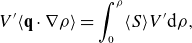 \begin{equation} V' \langle \textbf{q}\cdot \nabla \rho \rangle = \int _0^{\rho } \langle S\rangle V' {\rm d}\rho, \end{equation}
where brackets denote a flux surface average
 \begin{equation} \langle A\rangle = \frac {\int _0^{2\pi } \int _0^{2\pi } \sqrt {g} A {\rm d}\theta {\rm d}\zeta }{\int _0^{2\pi } \int _0^{2\pi } \sqrt {g} {\rm d}\theta {\rm d}\zeta } = \frac {1}{V'} \int _0^{2\pi } \int _0^{2\pi } \sqrt {g} A {\rm d}\theta {\rm d}\zeta, \end{equation}
where $\sqrt {g} = 1/\nabla \rho \cdot \nabla \theta \times \nabla \zeta$
is the Jacobian, and
$\sqrt {g} = 1/\nabla \rho \cdot \nabla \theta \times \nabla \zeta$
is the Jacobian, and $V' = {\rm d}V/{\rm d}\rho = \int _0^{2\pi } \int _0^{2\pi } \sqrt {g} {\rm d}\theta {\rm d}\zeta$
. To simplify this expression, we introduce the dimensionless functions
$V' = {\rm d}V/{\rm d}\rho = \int _0^{2\pi } \int _0^{2\pi } \sqrt {g} {\rm d}\theta {\rm d}\zeta$
. To simplify this expression, we introduce the dimensionless functions $\hat {V}' = V'/(4\pi ^2 a R)$
and
$\hat {V}' = V'/(4\pi ^2 a R)$
and $\hat {P}$
using
$\hat {P}$
using
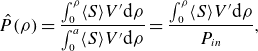 \begin{equation} \hat {P}(\rho ) = \frac {\int _0^{\rho } \langle S\rangle V' {\rm d}\rho }{\int _0^a \langle S\rangle V' {\rm d}\rho } = \frac {\int _0^{\rho } \langle S\rangle V' {\rm d}\rho }{P_{in}}, \end{equation}
where $P_{in}$
is the total net input power.
$P_{in}$
is the total net input power.
Next, a commonly employed model for drift-wave-like turbulent transport (Kotschenreuther et al. Reference Kotschenreuther, Dorland, Beer and Hammett1995; Dimits et al. Reference Dimits2000; Garbet et al. Reference Garbet2004) is introduced
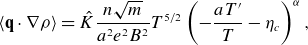 \begin{equation} \langle \textbf{q}\cdot \nabla \rho \rangle = \hat {K} \frac {n\sqrt {m}}{a^2e^2B^2} T^{5/2} \left(- \frac {aT'}{T} - \eta _c\right)^\alpha, \end{equation}
where we pull out crucial scalings associated with gyro-Bohm turbulence, the dimensionless function $\hat {K} = \hat {K}(\rho )$
contains all of the remaining parametric dependencies and in general is a function of the flux surface label
$\hat {K} = \hat {K}(\rho )$
contains all of the remaining parametric dependencies and in general is a function of the flux surface label $\rho$
,
$\rho$
, $T' = {\rm d}T/{\rm d}\rho$
and
$T' = {\rm d}T/{\rm d}\rho$
and $\eta _c = (a/L_T)_{crit}$
is the critical gradient for turbulent transport onset. Typically,
$\eta _c = (a/L_T)_{crit}$
is the critical gradient for turbulent transport onset. Typically, $\eta _c \sim 1$
and
$\eta _c \sim 1$
and $\alpha \sim 2 - 3$
from simulation studies, but we keep these factors general for the moment. Inserting these forms into (2.4), we have
$\alpha \sim 2 - 3$
from simulation studies, but we keep these factors general for the moment. Inserting these forms into (2.4), we have
 \begin{equation} T^{5/2} \left(- \frac {aT'}{T} - \eta _c\right)^{\alpha } = T_{GB}^{5/2} \frac {\hat {P}}{\hat {V}'\hat {K}\hat {N}} . \end{equation}
Here, the quantity $T_{GB}^{5/2} = a e^2 B^2 P_{in}/4\pi ^2 R \langle n\rangle \sqrt {m}$
is introduced which describes the essential gyro-Bohm prediction of the temperature, where
$T_{GB}^{5/2} = a e^2 B^2 P_{in}/4\pi ^2 R \langle n\rangle \sqrt {m}$
is introduced which describes the essential gyro-Bohm prediction of the temperature, where $\langle n\rangle$
is the volume-averaged density and
$\langle n\rangle$
is the volume-averaged density and $\hat {N} = n/\langle n\rangle$
. From this formula, we see that, at small radii, where the integrated input power is small (
$\hat {N} = n/\langle n\rangle$
. From this formula, we see that, at small radii, where the integrated input power is small ( $\hat {P} \rightarrow 0$
), the temperature gradient is largely set by the critical gradient. However, at larger radii (larger
$\hat {P} \rightarrow 0$
), the temperature gradient is largely set by the critical gradient. However, at larger radii (larger $\hat {P}$
) deviations from the critical gradient occur, with these deviations being amplified with large field strength as described by the
$\hat {P}$
) deviations from the critical gradient occur, with these deviations being amplified with large field strength as described by the $B$
dependence in
$B$
dependence in $T_{GB}$
and improved 3-D shaping through the parameter
$T_{GB}$
and improved 3-D shaping through the parameter $\hat {K}$
. Using this form for the heat flux, a closed form solution for
$\hat {K}$
. Using this form for the heat flux, a closed form solution for $T$
can be constructed
$T$
can be constructed
 \begin{equation} T(\rho ) = \left[T(a)^{5/2\alpha } e^{\frac {5}{2\alpha a}\int _\rho ^a \eta _c(y) {\rm d}y} + T_{GB}^{5/2\alpha } \int _{\rho }^a e^{\frac {5\eta _c}{2\alpha a}\int _{\rho }^{\rho '} \eta _c(y) {\rm d}y} \frac {5}{2\alpha a} \left(\frac {\hat {P}}{\hat {V}'\hat {K}}\right)^{1/\alpha } {\rm d}\rho '\right]^{2\alpha /5}.\end{equation}
In the small $B$
field limit,
$B$
field limit, $T_{GB} \rightarrow 0$
, the first term in this expression dominates and the temperature profile is determined by marginal stability conditions with the consequence that good plasma confinement requires an edge pedestal region (or H-mode) yielding high
$T_{GB} \rightarrow 0$
, the first term in this expression dominates and the temperature profile is determined by marginal stability conditions with the consequence that good plasma confinement requires an edge pedestal region (or H-mode) yielding high $T(a)$
. Conversely, the second term in the bracket will play a more important role at higher
$T(a)$
. Conversely, the second term in the bracket will play a more important role at higher $B$
and the confinement is given by gyro-Bohm scaling with
$B$
and the confinement is given by gyro-Bohm scaling with $T \sim P_{in}^{0.4} n^{-0.4} B^{0.8} (a/R)^{0.4}$
. Note that this expression is not unique to stellarators. Indeed, in an effort to avoid H-mode and associated edge localized modes, high performance L-mode is being sought as a plausible operational scenario for high-field tokamak reactors (Frank et al. Reference Frank2022).
$T \sim P_{in}^{0.4} n^{-0.4} B^{0.8} (a/R)^{0.4}$
. Note that this expression is not unique to stellarators. Indeed, in an effort to avoid H-mode and associated edge localized modes, high performance L-mode is being sought as a plausible operational scenario for high-field tokamak reactors (Frank et al. Reference Frank2022).
3. Optimization principles employed in stellarator generation
During the course of this study, a wide range of optimization strategies were employed. A broad set of aspect ratio ( $A = R/a, 5 \leqslant A \leqslant 11$
), toroidal field number
$A = R/a, 5 \leqslant A \leqslant 11$
), toroidal field number $2 \leqslant N \leqslant 6$
, neoclassical optimization approaches (QS and QI) and optimization frameworks were considered. Both the Simons stellarator optimization code (SIMSOPT) (Landreman et al. Reference Landreman, Medasani, Wechsung, Giuliani, Jorge and Zhu2021) and the Dudt-Egemen stellarator code (DESC) (Dudt & Kolemen Reference Dudt and Kolemen2020) were used. Generally, a two-stage optimization approach is implemented. Initial configuration generation uses a fixed boundary equilibrium in the physics optimization. For this first stage, the shape of the outer boundary is varied in order to optimally find a desirable magnetic configuration. The output of this process is a fixed boundary equilibrium Variational Methods Equilibrium Code (VMEC) (Hirshman & Whitson Reference Hirshman and Whitson1983) or DESC (Dudt & Kolemen Reference Dudt and Kolemen2020) solution that assumes the existence of flux surfaces. Subsequently, a coil optimization is performed, minimizing the normal component of the magnetic field at the desired plasma boundary subject to a number of engineering constraints on the coils.
$2 \leqslant N \leqslant 6$
, neoclassical optimization approaches (QS and QI) and optimization frameworks were considered. Both the Simons stellarator optimization code (SIMSOPT) (Landreman et al. Reference Landreman, Medasani, Wechsung, Giuliani, Jorge and Zhu2021) and the Dudt-Egemen stellarator code (DESC) (Dudt & Kolemen Reference Dudt and Kolemen2020) were used. Generally, a two-stage optimization approach is implemented. Initial configuration generation uses a fixed boundary equilibrium in the physics optimization. For this first stage, the shape of the outer boundary is varied in order to optimally find a desirable magnetic configuration. The output of this process is a fixed boundary equilibrium Variational Methods Equilibrium Code (VMEC) (Hirshman & Whitson Reference Hirshman and Whitson1983) or DESC (Dudt & Kolemen Reference Dudt and Kolemen2020) solution that assumes the existence of flux surfaces. Subsequently, a coil optimization is performed, minimizing the normal component of the magnetic field at the desired plasma boundary subject to a number of engineering constraints on the coils.
Multiple optimization targets were used during the course of this study. To encourage robust magnetic surface integrity, the rotational transform profile is constrained to avoid low-order rational surfaces. In many cases, consistency of the stellarator configuration with an island divertor solution is required. In this situation, the rotational transform at the edge is constrained to make a rational value ${{\iota\kern-1pt\!\mbox{-}\kern0.5pt}}(a) = N/M$
consistent with the toroidal field period. Avoidance of low-order rational surfaces then requires
${{\iota\kern-1pt\!\mbox{-}\kern0.5pt}}(a) = N/M$
consistent with the toroidal field period. Avoidance of low-order rational surfaces then requires $N/(M +1) \lt {{\iota\kern-1pt\!\mbox{-}\kern0.5pt}} \leqslant N/M$
for
$N/(M +1) \lt {{\iota\kern-1pt\!\mbox{-}\kern0.5pt}} \leqslant N/M$
for ${\rm d}{{\iota\kern-1pt\!\mbox{-}\kern0.5pt}}/{\rm d}\psi \gt 0$
at the edge. Local linear ideal MHD stability can be described by the Mercier criterion and ideal MHD ballooning theory (Dewar & Glasser Reference Dewar and Glasser1983). A commonly employed metric for neoclassical transport is
${\rm d}{{\iota\kern-1pt\!\mbox{-}\kern0.5pt}}/{\rm d}\psi \gt 0$
at the edge. Local linear ideal MHD stability can be described by the Mercier criterion and ideal MHD ballooning theory (Dewar & Glasser Reference Dewar and Glasser1983). A commonly employed metric for neoclassical transport is $\epsilon ^{3/2}_{eff}$
which is the amplitude of the neoclassical transport in the small (
$\epsilon ^{3/2}_{eff}$
which is the amplitude of the neoclassical transport in the small ( $1/\nu$
where
$1/\nu$
where $\nu$
is the collision frequency) collisionality regime (Nemov et al. Reference Nemov, Kasilov, Kernbichler and Heyn1999). The metric
$\nu$
is the collision frequency) collisionality regime (Nemov et al. Reference Nemov, Kasilov, Kernbichler and Heyn1999). The metric $\unicode{x1D6E4} _c$
is also commonly used to assess collisionless energetic particle confinement in stellarators (Nemov et al. Reference Nemov, Kasilov, Kernbichler and Leitold2008). Additionally, the
$\unicode{x1D6E4} _c$
is also commonly used to assess collisionless energetic particle confinement in stellarators (Nemov et al. Reference Nemov, Kasilov, Kernbichler and Leitold2008). Additionally, the $L_{\nabla \textbf{B}}$
metric (Kappel et al. Reference Kappel, Landreman and Malhotra2024) can be used as a measure of ‘coil buildability’. Large values of
$L_{\nabla \textbf{B}}$
metric (Kappel et al. Reference Kappel, Landreman and Malhotra2024) can be used as a measure of ‘coil buildability’. Large values of $L_{\nabla \textbf{B}}$
tend to correlate with a greater ease in constructing coils. Various formulae for these metrics are provided in Appendix A.
$L_{\nabla \textbf{B}}$
tend to correlate with a greater ease in constructing coils. Various formulae for these metrics are provided in Appendix A.
Different strategies are employed to obtain QS or QI equilibria. Optimizing for QS stellarators requires minimizing the non-symmetric components of $|B|$
in Boozer coordinates. The generation of QS configurations has been widely employed in the stellarator optimization community (Zarnstorff et al. Reference Zarnstorff2001; Bader et al. Reference Bader2020; Rodriguez et al. Reference Rodriguez, Helander and Bhattacharjee2020; Landreman & Paul Reference Landreman and Paul2022). To generate QI equilibria, a different approach is used. For QI, the alignment of the adiabatic invariant
$|B|$
in Boozer coordinates. The generation of QS configurations has been widely employed in the stellarator optimization community (Zarnstorff et al. Reference Zarnstorff2001; Bader et al. Reference Bader2020; Rodriguez et al. Reference Rodriguez, Helander and Bhattacharjee2020; Landreman & Paul Reference Landreman and Paul2022). To generate QI equilibria, a different approach is used. For QI, the alignment of the adiabatic invariant $J$
defined by
$J$
defined by
 \begin{equation} J = \int m v_{||} {\rm d}l, \end{equation}
with flux surfaces $\psi$
is sought,
$\psi$
is sought, $J = J(\psi )$
. Here,
$J = J(\psi )$
. Here, $m$
denotes particle mass. Additionally, we appeal to the max-J condition
$m$
denotes particle mass. Additionally, we appeal to the max-J condition $\partial J/\partial \psi \lt 0$
which is known to have benefits for trapped particle instabilities and associated turbulent transport (Helander et al. Reference Helander, Proll and Plunk2013; Alcuson et al. Reference Alcuson, Xanthopolous, Plunk, Helander, Wilms, Turkin, vanStechow and Grulke2020; Xanthopoulos et al. Reference Xanthopoulos, Bozhenkov, Beurkens, Smith, Plunk, Helander, Beidler, Alcuson, Alonso and Dinklage2020). Moreover, the max
$\partial J/\partial \psi \lt 0$
which is known to have benefits for trapped particle instabilities and associated turbulent transport (Helander et al. Reference Helander, Proll and Plunk2013; Alcuson et al. Reference Alcuson, Xanthopolous, Plunk, Helander, Wilms, Turkin, vanStechow and Grulke2020; Xanthopoulos et al. Reference Xanthopoulos, Bozhenkov, Beurkens, Smith, Plunk, Helander, Beidler, Alcuson, Alonso and Dinklage2020). Moreover, the max $J$
condition tends to correlate with the presence of a magnetic well, hence, good MHD stability. For QI, we also seek configurations where the local minima (maxima) of
$J$
condition tends to correlate with the presence of a magnetic well, hence, good MHD stability. For QI, we also seek configurations where the local minima (maxima) of $|B|$
along the field have a common value of
$|B|$
along the field have a common value of $B_{min}$
(
$B_{min}$
( $B_{max}$
). Alignment of local extrema (especially local minima) tends to be important for energetic particle confinement as well.
$B_{max}$
). Alignment of local extrema (especially local minima) tends to be important for energetic particle confinement as well.
Optimization to turbulent transport is an emerging area of stellarator design. There have been several approaches proposed in the stellarator community that aim to reduce turbulent transport in stellarators (Mynick et al. Reference Mynick, Pomphrey and Xanthopoulos2010; Xanthopoulos et al. Reference Xanthopoulos, Mynick, Helander, Turkin, Plunk, Jenko, Gorler, Told, Bird and Proll2014; Proll et al. Reference Proll, Mynick, Xanthopoulos, Lazerson and Faber2016; Terry et al. Reference Terry, Faber, Hegna, Mirnov, Pueschel and Whelan2018; Hegna et al. Reference Hegna, Terry and Faber2018; Hegna et al. Reference Hegna2022; Mackenbach et al. Reference Mackenbach, Proll and Helander2022; Jorge et al. Reference Jorge, Dorland, Kim, Landreman, Mandell, Merlo and Qian2023; Gerard et al. Reference Gerard, Puechscehl, Geiger, Mackenbach, Duff, Faber, Hegna and Terry2024; Goodman et al. Reference Goodman, Xanthopoulos, Plunk, Smith, Nührenberg, Beidler, Henneberg, Roberg-Clark, Drevlak and Helander2024; Roberg-Clark et al. Reference Roberg-Clark, Xanthopoulos and Plunk2024). Typically, these approaches rely on understanding some characteristic aspect of ion temperature gradient (ITG) or trapped electron mode (TEM) turbulent transport. Several of these proposed metrics have been included in the optimization schemes employed here. While some of these metrics have shown promise for some sub-classes of stellarators, no clear criterion has emerged that can be used to judge turbulent transport reduction for every stellarator design.
For Infinity Two, we developed a somewhat different approach to optimize for turbulent transport. For this exercise, we considered the operational scenario for a stellarator FPP. An important element of turbulent optimization is linked to the properties of the density profile envisioned for Infinity Two. A prominent feature for the configuration, as shown in figure 4, is a flat density profile inside $\rho \sim 0.6$
. Here,
$\rho \sim 0.6$
. Here, $\rho = \sqrt {s}$
where
$\rho = \sqrt {s}$
where $s = \psi /\psi _a$
in the toroidal flux normalized to its value at the plasma edge. This density profile is a natural consequence of using continuous pellet fueling in a stellarator reactor consistent with the intrinsic transport properties (Helander & Zocco Reference Helander and Zocco2018). While there exists some flexibility in pellet design, simple ablation physics modeling demonstrates a strong electron temperature dependence which restricts pellets from penetrating into regions with greater than
$s = \psi /\psi _a$
in the toroidal flux normalized to its value at the plasma edge. This density profile is a natural consequence of using continuous pellet fueling in a stellarator reactor consistent with the intrinsic transport properties (Helander & Zocco Reference Helander and Zocco2018). While there exists some flexibility in pellet design, simple ablation physics modeling demonstrates a strong electron temperature dependence which restricts pellets from penetrating into regions with greater than $T_e \sim 5$
keV (Parks & Turnbull Reference Parks and Turnbull1978; Zhang et al. Reference Zhang, McClenaghan, Parks, Lau and Wu2022; McClenaghan et al. Reference McClenaghan, Lao, Parks, Wu, Zhang and Chan2023). This fact and the absence of a prominent particle pinch produces nearly flat density profiles in the core and leads to a significant density gradient in a confinement zone defined by the region
$T_e \sim 5$
keV (Parks & Turnbull Reference Parks and Turnbull1978; Zhang et al. Reference Zhang, McClenaghan, Parks, Lau and Wu2022; McClenaghan et al. Reference McClenaghan, Lao, Parks, Wu, Zhang and Chan2023). This fact and the absence of a prominent particle pinch produces nearly flat density profiles in the core and leads to a significant density gradient in a confinement zone defined by the region $0.6 \lt \rho \lt 0.9$
.
$0.6 \lt \rho \lt 0.9$
.
The properties of the density profile in combination with the discussion at the end of § 2 dictates the turbulent transport optimization scheme. In seeking the maximal amount of fusion power, one would naturally focus on lowering the turbulent transport at larger radii due to the volumetric effect. As such, we focus on turbulent transport properties of the confinement zone. The large density gradient present in this region is strongly stabilizing to ITG-induced turbulent transport (Coppi et al. Reference Coppi, Rosenbluth and Sagdeev1967; Kotschenreuther et al. Reference Kotschenreuther, Liu, Mahajan, Hatch and Merlo2024). This fact, in and of itself, provides larger temperature gradients in this region. Indeed, this basic picture has been largely corroborated on pellet fueled discharges on W7-X where large ion temperatures have been achieved with density peaking (Bozhenov et al. Reference Bozhenov2020). However, as pointed out in (2.8) and (2.9), there is an additional benefit to improved transport by appealing to reduced stiffness at larger radii. For this goal, our effort focused on developing a physics informed turbulent transport model built from data gleaned from the Type One Energy configuration database at elevated density gradient ( $a/L_n = -(a/n_e) {\rm d}n_e/{\rm d}\rho \sim 3.0$
).
$a/L_n = -(a/n_e) {\rm d}n_e/{\rm d}\rho \sim 3.0$
).
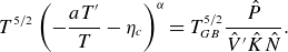
Fixed boundary stellarator configurations can be obtained using some combination of the above metrics in an optimization for different choices of aspect ratio, number of field periods, neoclassical optimization principle, optimization weightings and optimization algorithm. As of the writing of this manuscript more than 70,000 finite-pressure optimized stellarators have been generated. Each of these configurations can be assessed by a set of increasingly more complex computational tools. Assessment criterion for rotational transform properties, Mercier stability, $\epsilon _{eff}, \unicode{x1D6E4} _c$
, quasi-symmetry metrics and
$\epsilon _{eff}, \unicode{x1D6E4} _c$
, quasi-symmetry metrics and $L_{\nabla \textbf{B}}$
requires the evaluation of an analytic function. A scatter plot of a subset of the configurations in the dataset is shown in figure 1 as a function of
$L_{\nabla \textbf{B}}$
requires the evaluation of an analytic function. A scatter plot of a subset of the configurations in the dataset is shown in figure 1 as a function of $\unicode{x1D6E4} _c$
at normalized toroidal flux
$\unicode{x1D6E4} _c$
at normalized toroidal flux $s = \rho ^2 = 0.4$
and the maximum value of
$s = \rho ^2 = 0.4$
and the maximum value of $\epsilon _{eff}$
for
$\epsilon _{eff}$
for $0.1 \lt s \lt 1.0$
for both QS and QI configurations. These analytic criteria are evaluated for each configuration in the dataset, along with ideal ballooning stability properties computed using a re-implementation of the Code for Ballooning Rapid Analysis (COBRA)-VMEC code (Sanchez et al. Reference Sanchez, Hirshman and Wong2001) at multiple magnetic surfaces, and evaluations of the collisionless energetic particle confinement of fast ions using the sympletic integration methods for particle loss estimation (SIMPLE) code (Albert et al. Reference Albert, Kasilov and Kernbichler2020a
,
Reference Albert, Kasilov and Kernbichlerb
). In addition to assessing the stellarator designs, the dataset can also be used to test the viability of a particular reduced model measure against a more comprehensive theoretical model. For example in figure 2, we show a plot of SIMPLE’s measure of energetic ion confinement against
$0.1 \lt s \lt 1.0$
for both QS and QI configurations. These analytic criteria are evaluated for each configuration in the dataset, along with ideal ballooning stability properties computed using a re-implementation of the Code for Ballooning Rapid Analysis (COBRA)-VMEC code (Sanchez et al. Reference Sanchez, Hirshman and Wong2001) at multiple magnetic surfaces, and evaluations of the collisionless energetic particle confinement of fast ions using the sympletic integration methods for particle loss estimation (SIMPLE) code (Albert et al. Reference Albert, Kasilov and Kernbichler2020a
,
Reference Albert, Kasilov and Kernbichlerb
). In addition to assessing the stellarator designs, the dataset can also be used to test the viability of a particular reduced model measure against a more comprehensive theoretical model. For example in figure 2, we show a plot of SIMPLE’s measure of energetic ion confinement against $\unicode{x1D6E4} _c$
. The data indicate that a configuration with a very low value of
$\unicode{x1D6E4} _c$
. The data indicate that a configuration with a very low value of $\unicode{x1D6E4} _c$
is largely guaranteed to have excellent collisionless energetic ion confinement. However, the data also show that a low value of
$\unicode{x1D6E4} _c$
is largely guaranteed to have excellent collisionless energetic ion confinement. However, the data also show that a low value of $\unicode{x1D6E4} _c$
is not required for good energetic ion confinement.
$\unicode{x1D6E4} _c$
is not required for good energetic ion confinement.
Figure 1. A scatter plot of a subset of the configurations in the database as a function of $\unicode{x1D6E4} _c$
at
$\unicode{x1D6E4} _c$
at $s = 0.4$
and the maximum value of
$s = 0.4$
and the maximum value of $\epsilon _{eff}$
evaluated on the interval
$\epsilon _{eff}$
evaluated on the interval $0.1 \lt s \lt 1.0$
. Only those configurations that simultaneously satisfy
$0.1 \lt s \lt 1.0$
. Only those configurations that simultaneously satisfy $\unicode{x1D6E4} _c \lt 0.03$
and
$\unicode{x1D6E4} _c \lt 0.03$
and $\epsilon _{eff} \lt 0.01$
are included in the figure. The left plot corresponds to QI stellarators for
$\epsilon _{eff} \lt 0.01$
are included in the figure. The left plot corresponds to QI stellarators for $N = 2,3,4$
and the right corresponds to QS stellarators for
$N = 2,3,4$
and the right corresponds to QS stellarators for $N = 3,4,5,6$
.
$N = 3,4,5,6$
.

Figure 2. A comparison of collisionless guiding-center alpha-particle losses for particles born at $s = 0.4$
using the SIMPLE code vs the value of the
$s = 0.4$
using the SIMPLE code vs the value of the $\unicode{x1D6E4} _c$
metric at
$\unicode{x1D6E4} _c$
metric at $s =0.5$
.
$s =0.5$
.
Using the low-fidelity assessment tools, the database can be surveyed to find the better performing configurations. Subsequent analysis can then be performed on these configurations using higher-fidelity tools in the areas of macroscopic stability, energetic particle physics and turbulent transport. An important element of this analysis is the self-consistency of the bootstrap current profiles with the geometric properties of the configuration and plasma profiles. For this step, calculations of the bootstrap current using the SFINCS code (Landreman et al. Reference Landreman, Smith, Mollén and Helander2014) are iterated with VMEC equilibrium solutions. In practice, although not specifically accommodated in the optimization procedure, typically QI configurations will exhibit small bootstrap current density at all radii, and hence have minimal impact on the configuration. For the QS stellarators, the self-consistent bootstrap currents are a crucial element in the configuration optimization. Due to the high-field approach discussed previously, global MHD instability (long-wavelength modes) as predicted by TERPSICHORE (Anderson et al. Reference Anderson, Cooper, Gruber, Merazzi and Schwenn1990) is typically not violated until $\langle \beta \rangle$
values well above the envisioned
$\langle \beta \rangle$
values well above the envisioned $800$
MW operational point of Infinity Two. Turbulent transport is assessed using nonlinear flux-tube gyrokinetic simulations with the code GX (Mandell et al. Reference Mandell, Dorland, Abel, Gaur, Kim, Martin and Qian2024). Adiabatic electron simulations can be performed to address ITG properties in the electrostatic limit. However, in practice, non-adiabatic electron calculations are required to obtain predictions of the turbulent transport at the fidelity required to judge the capabilities of a configuration. In particular, it is important to perform these calculations at the relevant
$800$
MW operational point of Infinity Two. Turbulent transport is assessed using nonlinear flux-tube gyrokinetic simulations with the code GX (Mandell et al. Reference Mandell, Dorland, Abel, Gaur, Kim, Martin and Qian2024). Adiabatic electron simulations can be performed to address ITG properties in the electrostatic limit. However, in practice, non-adiabatic electron calculations are required to obtain predictions of the turbulent transport at the fidelity required to judge the capabilities of a configuration. In particular, it is important to perform these calculations at the relevant $\langle \beta \rangle$
and collisionality to provide a more comprehensive understanding of the turbulent transport. One important element of these assessments is the proximity of the configurations to ideal ballooning stability boundaries as kinetic ballooning modes (KBMs) generally provide vigorous turbulent transport once ballooning stability boundaries are breached and may be an issue at
$\langle \beta \rangle$
and collisionality to provide a more comprehensive understanding of the turbulent transport. One important element of these assessments is the proximity of the configurations to ideal ballooning stability boundaries as kinetic ballooning modes (KBMs) generally provide vigorous turbulent transport once ballooning stability boundaries are breached and may be an issue at $\langle \beta \rangle$
values below the critical value from ideal MHD theory (Aleynikova et al. Reference Aleynikova, Zocco, Xanthopoulos, Helander and Nührenberg2018; McKinney et al. Reference McKinney, Pueschel, Faber, Hegna, Ishizawa and Terry2021; Mulholland et al. Reference Mulholland, Aleynikova, Faber, Pueschel, Proll, Hegna, Terry and Nührenberg2023, Reference Mulholland, Pueschel, Proll, Aleynikova, Faber, Terry, Hegna and Nührenberg2025). To address this issue,
$\langle \beta \rangle$
values below the critical value from ideal MHD theory (Aleynikova et al. Reference Aleynikova, Zocco, Xanthopoulos, Helander and Nührenberg2018; McKinney et al. Reference McKinney, Pueschel, Faber, Hegna, Ishizawa and Terry2021; Mulholland et al. Reference Mulholland, Aleynikova, Faber, Pueschel, Proll, Hegna, Terry and Nührenberg2023, Reference Mulholland, Pueschel, Proll, Aleynikova, Faber, Terry, Hegna and Nührenberg2025). To address this issue, $\langle \beta \rangle$
scans are performed in the high-fidelity turbulent transport assessments to test the robustness of the configuration.
$\langle \beta \rangle$
scans are performed in the high-fidelity turbulent transport assessments to test the robustness of the configuration.
Among a subset of the better performing of the configurations using the high-fidelity tools, a filamentary coil set is designed. From the coil designs, a free-boundary equilibrium is constructed with self-consistent bootstrap current profile. Free-boundary equilibria are then reassessed using the collection of theoretical tools described previously. In these studies, some level of profile sensitivity is performed to deduce the robustness of the configuration performance. For those configurations using an island divertor, care is taken to guarantee an edge resonant surface value in the rotational transform profile. Vacuum calculations of the coil set provide information about the vacuum magnetic island structure at the edge. For finite $\langle \beta \rangle$
plasmas, the HINT code (Suzuki et al. Reference Suzuki, Nakajima, Watanabe, Nakamura and Hayashi2006; Suzuki Reference Suzuki2017) is employed to provide a more accurate prediction of the configuration topology. HINT is a 3-D MHD equilibrium code that does not impose the presence of magnetic surfaces and allows for magnetic islands and regions of magnetic stochasticity. To assess the viability of stellarator fusion pilot plant, the configuration is scaled to appropriate size so as to accommodate an
$\langle \beta \rangle$
plasmas, the HINT code (Suzuki et al. Reference Suzuki, Nakajima, Watanabe, Nakamura and Hayashi2006; Suzuki Reference Suzuki2017) is employed to provide a more accurate prediction of the configuration topology. HINT is a 3-D MHD equilibrium code that does not impose the presence of magnetic surfaces and allows for magnetic islands and regions of magnetic stochasticity. To assess the viability of stellarator fusion pilot plant, the configuration is scaled to appropriate size so as to accommodate an $800$
MW DT fusion plasma with averaged density set by the Sudo limit (
$800$
MW DT fusion plasma with averaged density set by the Sudo limit ( $f_S = \langle n_e\rangle /n_{{Sudo}} \sim 1$
) and confinement scaling with some improvement over the ISS04 scaling law. Necessarily, there is some flexibility in operational scenario built into the rescaling exercise. The resulting configuration then undergoes a comprehensive evaluation of the core plasma confinement properties, divertor region and blanket design using state-of-the-art computational tools.
$f_S = \langle n_e\rangle /n_{{Sudo}} \sim 1$
) and confinement scaling with some improvement over the ISS04 scaling law. Necessarily, there is some flexibility in operational scenario built into the rescaling exercise. The resulting configuration then undergoes a comprehensive evaluation of the core plasma confinement properties, divertor region and blanket design using state-of-the-art computational tools.
4. Infinity two properties
In the following, we introduce the basic properties of Infinity Two. The configuration relies on a QI neoclassical optimization strategy with $N = 4$
field periods, aspect ratio
$N = 4$
field periods, aspect ratio $A = 10$
and volume-averaged magnetic field
$A = 10$
and volume-averaged magnetic field $\langle B\rangle = 9$
T. Other parameters pertinent to an
$\langle B\rangle = 9$
T. Other parameters pertinent to an $800$
MW DT fusion scenario for this stellarator are provided in table 1. We note that this operating point is not constrained by any operational limit. Indeed, as shown in the accompanying paper from Guttenfelder et al. (Reference Guttenfelder2025), ignited DT fusion power scenarios are available to this configuration as designed at higher plasma density. It is also possible to envision that this configuration could be operated at smaller physical size. However, reducing the minor radius introduces additional challenges to coil design as well as putting additional constraints on the exhaust system and enhancing the neutron wall loading and alpha-particle-induced heat loads on the first wall. The required fidelity on the required 3-D shaping from coils is complicated by the needs of a blanket and shielding of sufficient thickness. We have not tried to provide an overall optimization of the machine size that accounts for all of these competing effects. Rather, this study indicates that, from a plasma physics perspective, there is considerable flexibility in device size and/or DT fusion operating point to accommodate a working stellarator FPP.
$800$
MW DT fusion scenario for this stellarator are provided in table 1. We note that this operating point is not constrained by any operational limit. Indeed, as shown in the accompanying paper from Guttenfelder et al. (Reference Guttenfelder2025), ignited DT fusion power scenarios are available to this configuration as designed at higher plasma density. It is also possible to envision that this configuration could be operated at smaller physical size. However, reducing the minor radius introduces additional challenges to coil design as well as putting additional constraints on the exhaust system and enhancing the neutron wall loading and alpha-particle-induced heat loads on the first wall. The required fidelity on the required 3-D shaping from coils is complicated by the needs of a blanket and shielding of sufficient thickness. We have not tried to provide an overall optimization of the machine size that accounts for all of these competing effects. Rather, this study indicates that, from a plasma physics perspective, there is considerable flexibility in device size and/or DT fusion operating point to accommodate a working stellarator FPP.
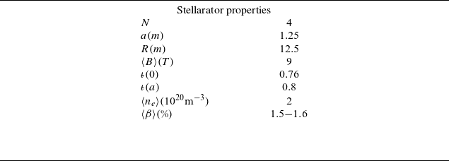
Table 1. Operational parameters of Infinity Two for $800$
MW DT fusion scenario.
$800$
MW DT fusion scenario.
Cross-sectional shapes of the fixed boundary equilibrium are shown in figure 3. As shown in the right panel, the $|B|$
contours close poloidally, indicative of a QI stellarator. The rotational transform profile for this configuration is shown on the left of figure 4. The configuration has relatively small averaged magnetic shear with
$|B|$
contours close poloidally, indicative of a QI stellarator. The rotational transform profile for this configuration is shown on the left of figure 4. The configuration has relatively small averaged magnetic shear with $0.75 \lt {{\iota\kern-1pt\!\mbox{-}\kern0.5pt}} \leqslant 0.8$
. The value of
$0.75 \lt {{\iota\kern-1pt\!\mbox{-}\kern0.5pt}} \leqslant 0.8$
. The value of ${{\iota\kern-1pt\!\mbox{-}\kern0.5pt}}(a) = 0.8$
is chosen so as to accommodate a
${{\iota\kern-1pt\!\mbox{-}\kern0.5pt}}(a) = 0.8$
is chosen so as to accommodate a $N = 4, M = 5$
island divertor at the plasma boundary. The rest of figure 4 shows the density, electron temperature and ion temperature profiles as a function of
$N = 4, M = 5$
island divertor at the plasma boundary. The rest of figure 4 shows the density, electron temperature and ion temperature profiles as a function of $\rho$
. The density profile is flat inside
$\rho$
. The density profile is flat inside $\rho \approx 0.6$
due to the fueling and transport optimization scheme discussed previously. This profile shape provides a peaking factor
$\rho \approx 0.6$
due to the fueling and transport optimization scheme discussed previously. This profile shape provides a peaking factor $n_e(0)/\langle n_e\rangle = 1.37$
and the ratio of axis to edge separatrix density is
$n_e(0)/\langle n_e\rangle = 1.37$
and the ratio of axis to edge separatrix density is $n_e(0)/n_{e}(1) = 4.0$
. The temperature profiles are constructed for nominal
$n_e(0)/n_{e}(1) = 4.0$
. The temperature profiles are constructed for nominal $800$
MW DT fusion conditions and a transport model indicative of gyro-Bohm-like turbulent transport. The edge temperature is assumed to be
$800$
MW DT fusion conditions and a transport model indicative of gyro-Bohm-like turbulent transport. The edge temperature is assumed to be $T_e(1) = 0.1$
keV and has peaking factor
$T_e(1) = 0.1$
keV and has peaking factor $T_{e}(0)/\langle T_e\rangle = 2.3$
with
$T_{e}(0)/\langle T_e\rangle = 2.3$
with $T_{e}(0)/T_{i}(0) = 1.25$
. These profiles were largely used in our optimization studies to scope out configuration properties. Subsequently, we use the T3D-GX-SFINCS transport framework to produce self-consistent calculations of the actual temperature profiles based on nonlinear gyrokinetic turbulent transport and neoclassical transport calculations. While there are some features that are different in the two profiles, the profiles shown in figure 4 are sufficient for many of the assessments. Profile differences result in small differences in volume-averaged beta for an
$T_{e}(0)/T_{i}(0) = 1.25$
. These profiles were largely used in our optimization studies to scope out configuration properties. Subsequently, we use the T3D-GX-SFINCS transport framework to produce self-consistent calculations of the actual temperature profiles based on nonlinear gyrokinetic turbulent transport and neoclassical transport calculations. While there are some features that are different in the two profiles, the profiles shown in figure 4 are sufficient for many of the assessments. Profile differences result in small differences in volume-averaged beta for an $800$
MW scenario, with
$800$
MW scenario, with $\langle \beta \rangle = 1.6\,\%$
for the profiles in figure 4 and
$\langle \beta \rangle = 1.6\,\%$
for the profiles in figure 4 and $\langle \beta \rangle = 1.5\,\%$
for more realistic T3D-based profiles.
$\langle \beta \rangle = 1.5\,\%$
for more realistic T3D-based profiles.
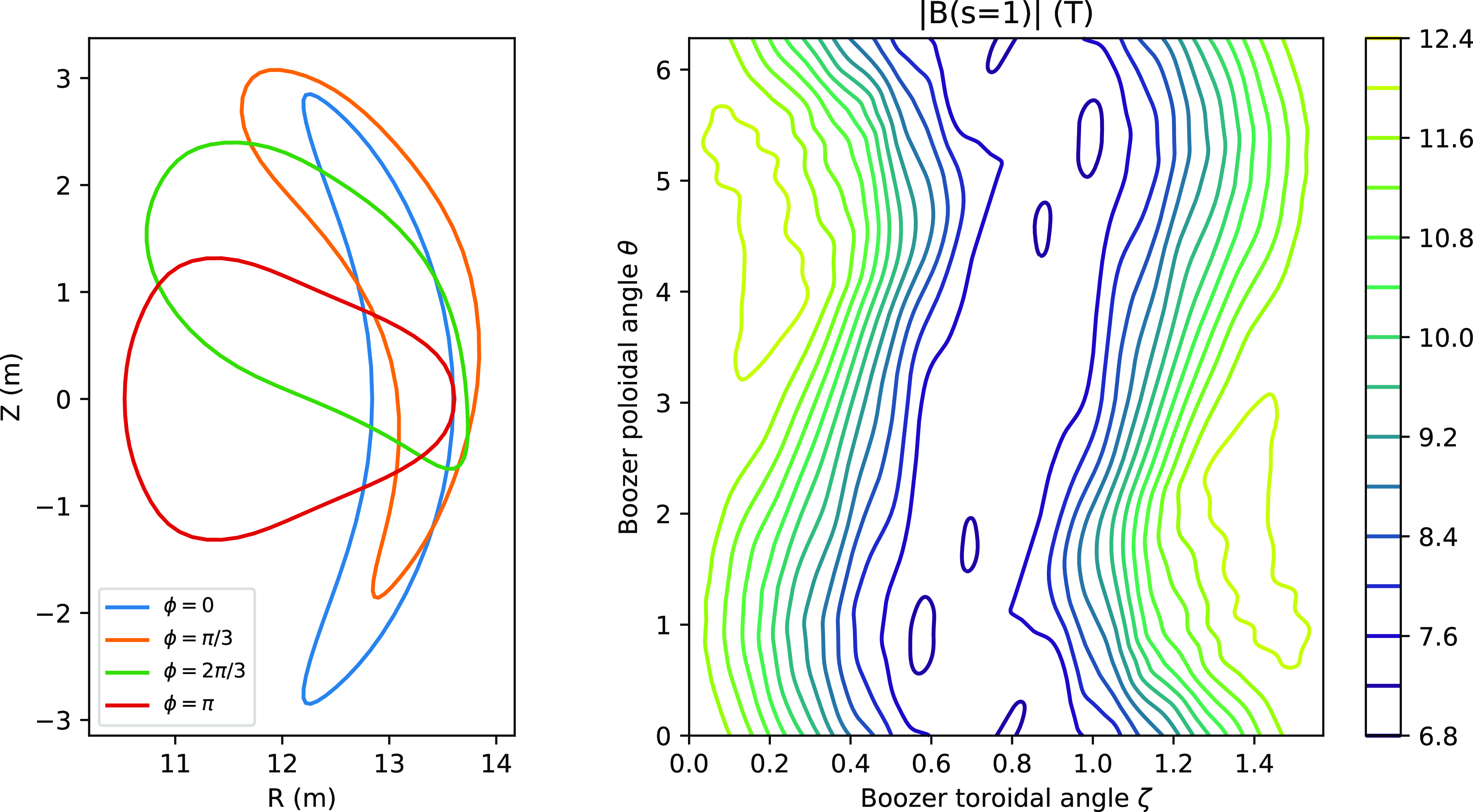
Figure 3. Cross-sectional shapes of the free-boundary equilibrium on the left at different geometric torodial angle $\phi$
locations. The right panel shows
$\phi$
locations. The right panel shows $|B|$
contours on the plasma boundary as a function of the Boozer angles.
$|B|$
contours on the plasma boundary as a function of the Boozer angles.
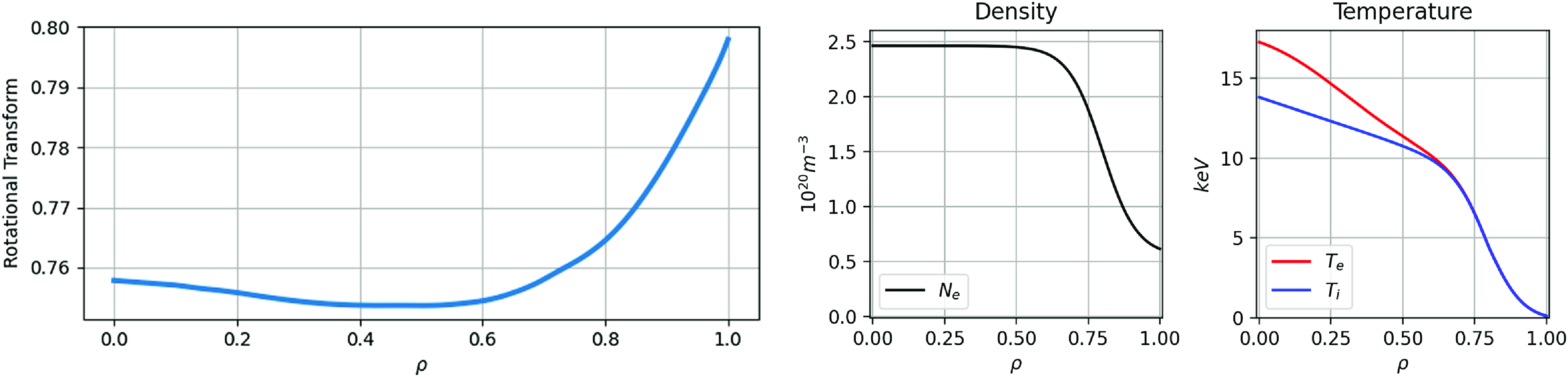
Figure 4. From left to right, plots of the rotational transform, the density profile and the ion and electron temperature profiles as a function of the flux surface label $\rho$
.
$\rho$
.
Coils for Infinity Two are constructed using the SIMSOPT optimization package (Landreman et al. Reference Landreman, Medasani, Wechsung, Giuliani, Jorge and Zhu2021). Our modular coil set is constructed with six coils per half-period. These coils were designed accounting for several engineering constraints, such as local coil curvature, coil planarity, port access and compatibility with maintenance schemes. For this study, we chose to rely exclusively on modular coils to produce the desired magnetic field. The coil system can be simplified and adjusted to satisfy additional engineering requirements via the use of planar coils and trim coils. Initially, a filamentary coil set was designed which has minimum filament-to-filament separation of $0.66$
m and minimum filament-to-plasma distance of
$0.66$
m and minimum filament-to-plasma distance of $1.21$
m. The minimum radius of curvature of the filaments is
$1.21$
m. The minimum radius of curvature of the filaments is $0.52$
m, and the maximum mean squared curvature (Giuliani et al. Reference Giuliani, Wechsung, Stadler, Cerfon and Landreman2022; Wechsung et al. Reference Wechsung, Giuliani, Landreman, Cerfon and Stadler2022) is
$0.52$
m, and the maximum mean squared curvature (Giuliani et al. Reference Giuliani, Wechsung, Stadler, Cerfon and Landreman2022; Wechsung et al. Reference Wechsung, Giuliani, Landreman, Cerfon and Stadler2022) is $0.8$
m
$0.8$
m $^{-2}$
.
$^{-2}$
.
The filamentary coils provide the basis for finite-build coil optimization, in which one determines an optimal coil pack configuration for each filament. The coil set with finite build is shown in figure 5. The first three of the unique coil shapes (the light gray, light blue and dark blue coils of figures 5 and 6) have an approximately elliptic shape with relatively small non-planar excursions. Coils $4$
(dark gray) and
$4$
(dark gray) and $5$
(dark purple) provide the bulk of the 3-D shaping with coil 4 carrying the largest current of the coil set and showing the largest excursions from planarity. With finite build, the minimum coil-to-plasma distance for coil 4 is
$5$
(dark purple) provide the bulk of the 3-D shaping with coil 4 carrying the largest current of the coil set and showing the largest excursions from planarity. With finite build, the minimum coil-to-plasma distance for coil 4 is $0.8$
m. For all other coils, the minimum coil-to-plasma distance is
$0.8$
m. For all other coils, the minimum coil-to-plasma distance is $1.0$
m. The coil-to-plasma distance has a large variation as a function of both poloidal and toroidal angles. The minimum coil-to-coil distance (
$1.0$
m. The coil-to-plasma distance has a large variation as a function of both poloidal and toroidal angles. The minimum coil-to-coil distance ( $\sim 4.3$
cm) occurs between coils 2 and 3.
$\sim 4.3$
cm) occurs between coils 2 and 3.

Figure 5. A top down view of a coil set with finite build for Infinity Two. There are six coils per half-period.
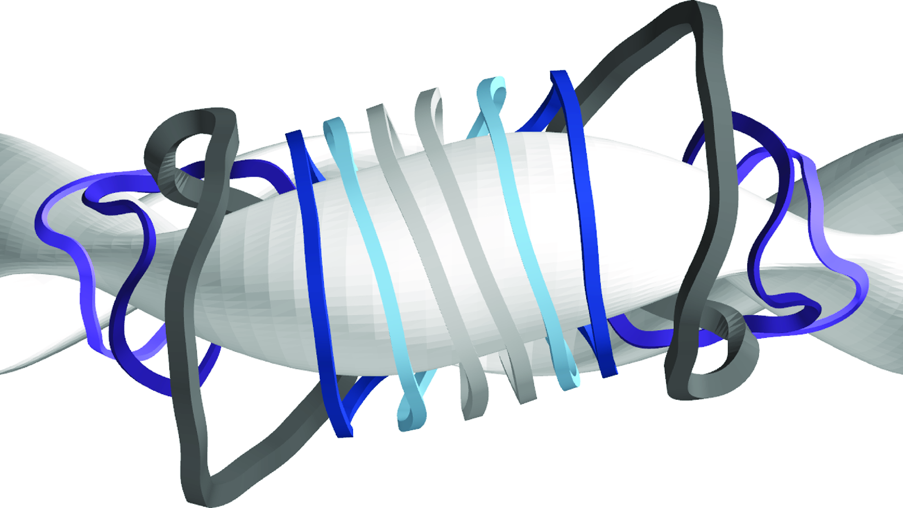
Figure 6. A side view of Infinity Two’s coil set demonstrating that a plane exists separating the two light gray coils at the field period boundary. This property can be exploited for sector maintenance as the machine can be split into four sections.
Several coil sets were designed to reproduce the desired physics properties of the magnetic configuration. The coil set we have elected to show here has several beneficial features. Notably, the relatively large non-planar excursion of coil 4 allows for ample port access for diagnostics, particle and/or heating sources. In figure 6, a side view of the coil set is shown. Note that a plane exists between the two symmetric copies of coil 1 from adjacent field periods which can be exploited for sector maintenance, since it allows clash free extraction of a given field period. An estimate of the magnetic field at the base of the coils is performed using a simplified multi-turn cable description of that coil. The largest field strength occurs on coil $4$
where the average of the maximum values of the magnetic field in each cross-section is typically
$4$
where the average of the maximum values of the magnetic field in each cross-section is typically $\sim 18-21$
T, values that are considered feasible (Sanabria et al. Reference Sanabria2024). However, there are localized maximum peaks in field strength whose value depends sensitively on the details of the coil internal structure. These have not been modeled for the present physics study but will be as the engineering design moves forward.
$\sim 18-21$
T, values that are considered feasible (Sanabria et al. Reference Sanabria2024). However, there are localized maximum peaks in field strength whose value depends sensitively on the details of the coil internal structure. These have not been modeled for the present physics study but will be as the engineering design moves forward.
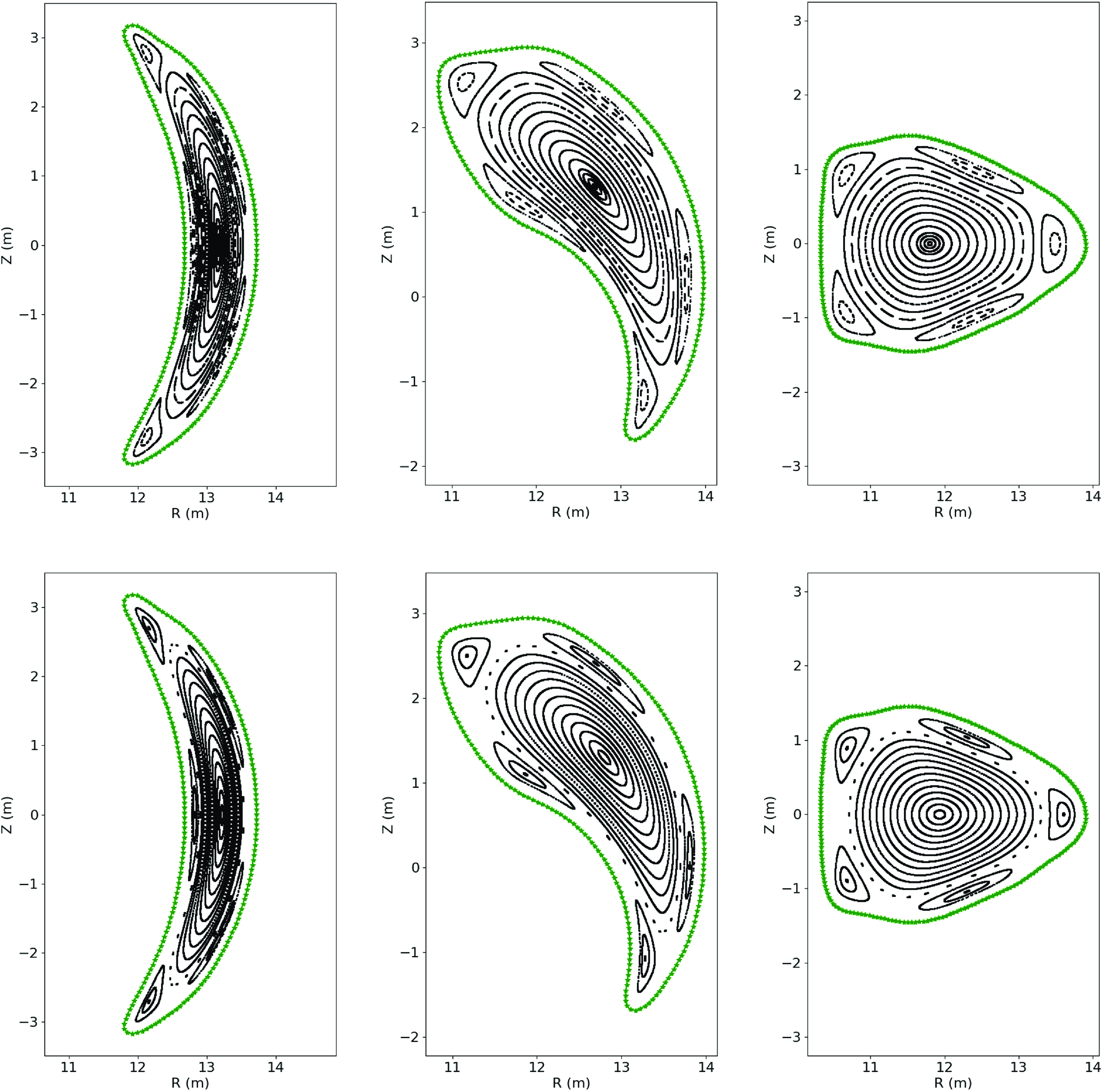
Figure 7. Poincaré sections of the vacuum configuration (top row) and the configuration at $\langle \beta \rangle = 1.6\,\%$
from HINT calculations (bottom row). The three plots correspond to the toroidal angle
$\langle \beta \rangle = 1.6\,\%$
from HINT calculations (bottom row). The three plots correspond to the toroidal angle $\phi = 0, \pi /8, \pi /4$
from left to right.
$\phi = 0, \pi /8, \pi /4$
from left to right.
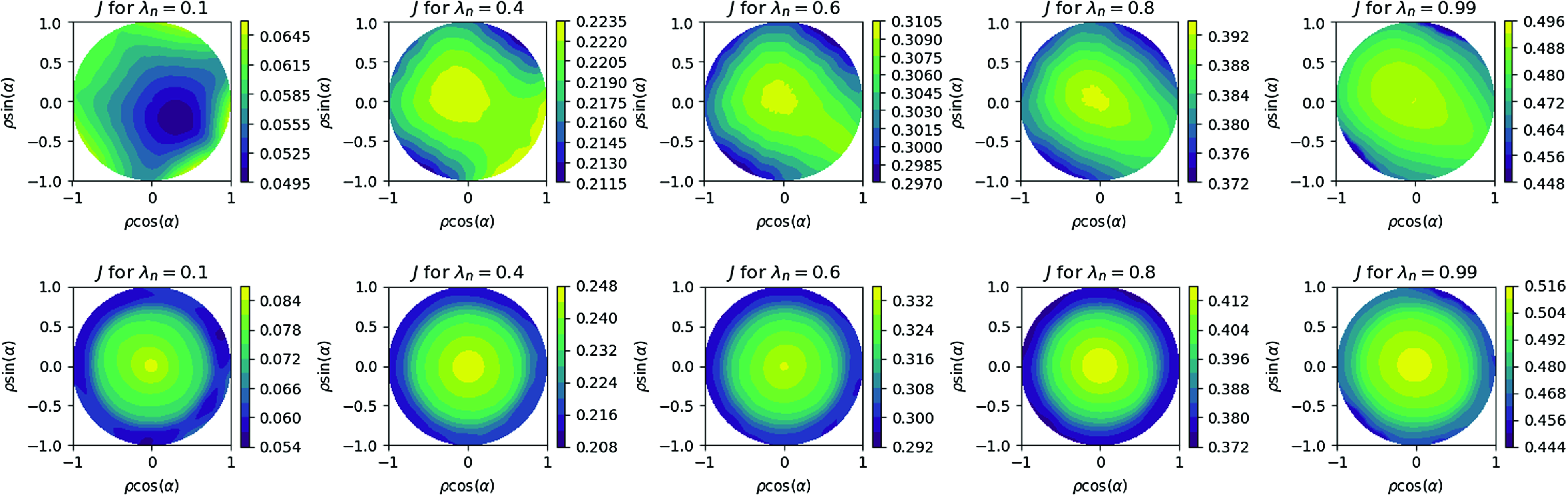
Figure 8. Contours of the second adiabatic invariant $J$
for vacuum (top row) and for the
$J$
for vacuum (top row) and for the $\langle \beta \rangle =1.6\,\%$
operating point (bottom row). The five entries correspond to different trapped particles as labeled by the pitch angle variable
$\langle \beta \rangle =1.6\,\%$
operating point (bottom row). The five entries correspond to different trapped particles as labeled by the pitch angle variable $\lambda _n$
.
$\lambda _n$
.
The coils largely reproduce the excellent confinement properties of the fixed boundary configuration. In figure 7, a plot of the vacuum magnetic surfaces for the coil set is shown on the top line at toroidal locations $\phi = 0, \pi /8, \pi /4$
, respectively. The core region of the stellarator shows a robust set of magnetic surfaces and a prominent
$\phi = 0, \pi /8, \pi /4$
, respectively. The core region of the stellarator shows a robust set of magnetic surfaces and a prominent $N/M = 4/5$
magnetic island at the edge to be used as a divertor. The bottom set of Poincaré sections in figure 7 are produced from a HINT (Suzuki Reference Suzuki2017) calculation at the nominal
$N/M = 4/5$
magnetic island at the edge to be used as a divertor. The bottom set of Poincaré sections in figure 7 are produced from a HINT (Suzuki Reference Suzuki2017) calculation at the nominal $\langle \beta \rangle = 1.6 \,\%$
operating point at the same set of toroidal locations. The HINT calculations are carried out using the free-boundary VMEC equilibrium (Hirshman et al. Reference Hirshman, van RIJ and Merkel1986) as an initial condition. However, HINT subsequently relies on a relaxation algorithm to find an MHD equilibrium that eliminates the requirement of nested topologically toroidal flux surfaces present in VMEC. As such, magnetic islands and regions of magnetic stochasticity can form consistent with solutions to the MHD equilibrium equations. The HINT calculations of figure 7 show the magnetic surfaces in the core remain intact while an
$\langle \beta \rangle = 1.6 \,\%$
operating point at the same set of toroidal locations. The HINT calculations are carried out using the free-boundary VMEC equilibrium (Hirshman et al. Reference Hirshman, van RIJ and Merkel1986) as an initial condition. However, HINT subsequently relies on a relaxation algorithm to find an MHD equilibrium that eliminates the requirement of nested topologically toroidal flux surfaces present in VMEC. As such, magnetic islands and regions of magnetic stochasticity can form consistent with solutions to the MHD equilibrium equations. The HINT calculations of figure 7 show the magnetic surfaces in the core remain intact while an $N/M = 4/5$
island chain is a feature of the edge, largely in accordance with the vacuum magnetic field.
$N/M = 4/5$
island chain is a feature of the edge, largely in accordance with the vacuum magnetic field.
In figure 8, we plot contours of the second adiabatic invariant, as defined in (3.1) for different choices of the pitch angle variable $\lambda _n$
for the vacuum and the
$\lambda _n$
for the vacuum and the $\langle \beta \rangle = 1.6\,\%$
equilibrium. Here,
$\langle \beta \rangle = 1.6\,\%$
equilibrium. Here, $\lambda _n^2 = B_{max}(1 - \unicode{x03BC} B_{min}/\mathcal {E})/(B_{max} - B_{min})$
denotes a particle with energy
$\lambda _n^2 = B_{max}(1 - \unicode{x03BC} B_{min}/\mathcal {E})/(B_{max} - B_{min})$
denotes a particle with energy $\mathcal {E}$
and magnetic moment
$\mathcal {E}$
and magnetic moment $\mu$
moving along a field line with minimum (maximum) value of magnetic field strength given by
$\mu$
moving along a field line with minimum (maximum) value of magnetic field strength given by $B_{min}$
(
$B_{min}$
( $B_{max}$
);
$B_{max}$
); $\lambda _n \rightarrow 0$
denotes deeply trapped particles and
$\lambda _n \rightarrow 0$
denotes deeply trapped particles and $\lambda _n \rightarrow 1$
denotes barely trapped particles. In these plots in polar coordinates, the flux surface label
$\lambda _n \rightarrow 1$
denotes barely trapped particles. In these plots in polar coordinates, the flux surface label $\rho$
and the field line angle label
$\rho$
and the field line angle label $\alpha$
are mapped to the radial and angle coordinates, respectively. In the ideal limit,
$\alpha$
are mapped to the radial and angle coordinates, respectively. In the ideal limit, $J = J(\psi )$
, the
$J = J(\psi )$
, the $J$
contours correspond to surfaces of constant radius. Note that for this configuration, the desired condition
$J$
contours correspond to surfaces of constant radius. Note that for this configuration, the desired condition $\partial J/\partial \psi \lt 0$
holds for all trapped particles at the operating beta, and also holds for most of phase space in vacuum.
$\partial J/\partial \psi \lt 0$
holds for all trapped particles at the operating beta, and also holds for most of phase space in vacuum.
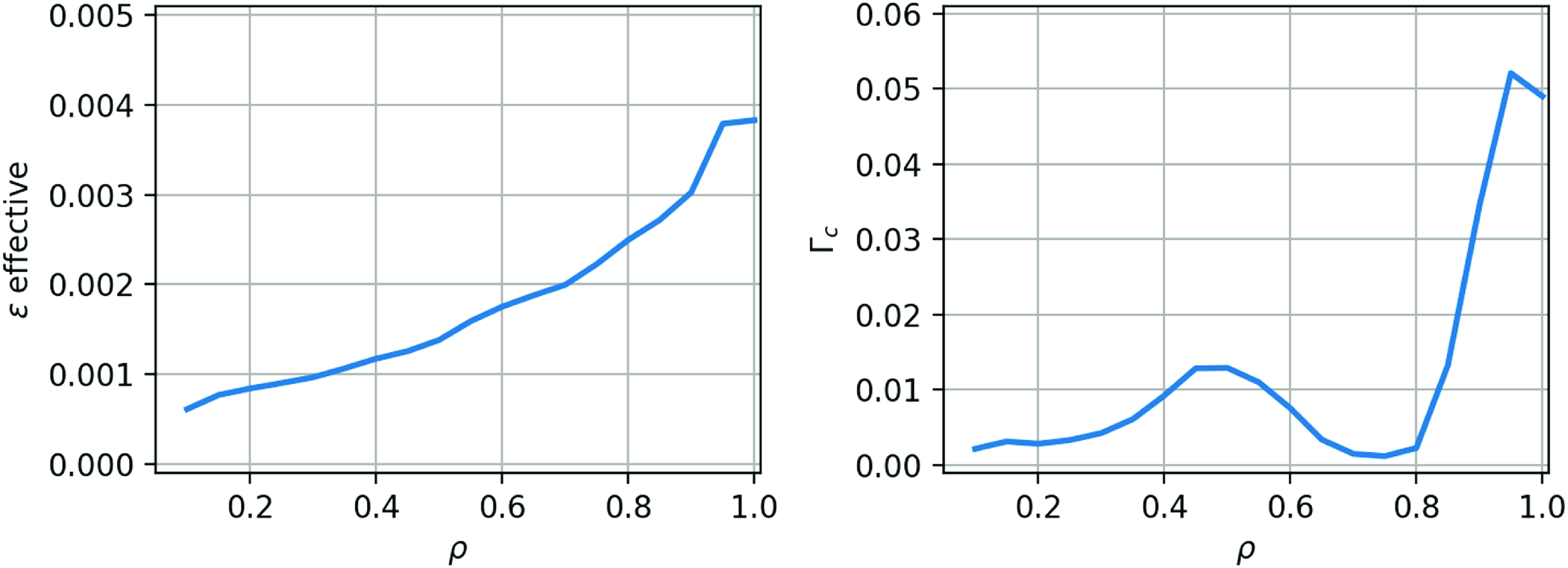
Figure 9. Plots of the quantities $\epsilon _{eff}$
and
$\epsilon _{eff}$
and $\unicode{x1D6E4} _c$
as a function of
$\unicode{x1D6E4} _c$
as a function of $\rho$
for the Infinity Two free-boundary equilibrium.
$\rho$
for the Infinity Two free-boundary equilibrium.
In figure 9, plots of the neoclassical transport metric $\epsilon _{eff}$
and the energetic particle metric
$\epsilon _{eff}$
and the energetic particle metric $\unicode{x1D6E4} _c$
as a function of
$\unicode{x1D6E4} _c$
as a function of $\rho$
are plotted for free-boundary VMEC equilibrium. For the sake of consistency, all the free-boundary equilibrium results shown in this article and the series of accompanying articles were obtained with a filamentary representation of the coils, since that representation was used early on for some of our most computationally intensive and time consuming calculations. However, we verified with a free-boundary VMEC computation that the finite-build coils generate an equilibrium that is nearly indistinguishable from the equilibrium corresponding to the filamentary coil approximation. As an illustration of this, figure 10 shows the Fourier spectra of
$\rho$
are plotted for free-boundary VMEC equilibrium. For the sake of consistency, all the free-boundary equilibrium results shown in this article and the series of accompanying articles were obtained with a filamentary representation of the coils, since that representation was used early on for some of our most computationally intensive and time consuming calculations. However, we verified with a free-boundary VMEC computation that the finite-build coils generate an equilibrium that is nearly indistinguishable from the equilibrium corresponding to the filamentary coil approximation. As an illustration of this, figure 10 shows the Fourier spectra of $|B|$
in Boozer coordinates as a function of the normalized toroidal flux
$|B|$
in Boozer coordinates as a function of the normalized toroidal flux $s$
for both filamentary and multi-filament finite-build free-boundary equilibria. The spectra are nearly identical, expect for the presence of a small mode (marked with a cross in the figure) for the multi-filament coils that was absent for the single-filament coils. We verified that the presence of this small mode did not modify the
$s$
for both filamentary and multi-filament finite-build free-boundary equilibria. The spectra are nearly identical, expect for the presence of a small mode (marked with a cross in the figure) for the multi-filament coils that was absent for the single-filament coils. We verified that the presence of this small mode did not modify the $\epsilon ^{3/2}_{eff}$
and
$\epsilon ^{3/2}_{eff}$
and $\unicode{x1D6E4} _c$
and Mercier criterion radial profiles, nor the geometric quantities impacting MHD stability and turbulent transport properties, except at the plasma edge.
$\unicode{x1D6E4} _c$
and Mercier criterion radial profiles, nor the geometric quantities impacting MHD stability and turbulent transport properties, except at the plasma edge.

Figure 10. The top 20 Boozer modes at the last closed flux surface for the single-filament coils (solid lines) and multifilament coils (dashed lines); most are indistinguishable by eye. One smaller mode (marked with a cross) for the multifilament coils makes an appearance in the top 20 that did not for the single-filament coils.
For all of the assessments of these configurations, a self-consistent bootstrap current profile is calculated consistent with ion-root ambipolar electric fields ( $E_r$
). In figure 11,
$E_r$
). In figure 11, $E_r$
and bootstrap current (
$E_r$
and bootstrap current ( $\langle \textbf{J}\cdot \textbf{B}\rangle _{bootstrap}$
) profiles are plotted as a function of
$\langle \textbf{J}\cdot \textbf{B}\rangle _{bootstrap}$
) profiles are plotted as a function of $\rho$
for the
$\rho$
for the $\langle \beta \rangle = 1.6\,\%$
base Infinity Two scenario. Two cases are considered, one with a two-species electron-hydrogen plasma (green) and one with multiple ion (black) species (D, T, He, Ne, W with fractional densities
$\langle \beta \rangle = 1.6\,\%$
base Infinity Two scenario. Two cases are considered, one with a two-species electron-hydrogen plasma (green) and one with multiple ion (black) species (D, T, He, Ne, W with fractional densities $0.425,0.425,0.05, 0.0046, 10^{-5}$
, respectively). While the multi-ion case has only one stable root throughout the cross-section, the electron-hydrogen case has both stable ion and electron roots very near
$0.425,0.425,0.05, 0.0046, 10^{-5}$
, respectively). While the multi-ion case has only one stable root throughout the cross-section, the electron-hydrogen case has both stable ion and electron roots very near $\rho = 0$
. In either case,
$\rho = 0$
. In either case, $E_r$
is quite small near the magnetic axis. The total bootstrap current for this configuration is quite small,
$E_r$
is quite small near the magnetic axis. The total bootstrap current for this configuration is quite small, $I_{bootstrap} \sim 2$
kA. This produces very small changes (
$I_{bootstrap} \sim 2$
kA. This produces very small changes ( $\Delta {{\iota\kern-1pt\!\mbox{-}\kern0.5pt}}_{bootstrap} \sim 0.001$
) to the rotational transform profile. The smallness of the bootstrap current is not required in the optimization scheme, but is a general feature of QI stellarators (Helander Reference Helander2014).
$\Delta {{\iota\kern-1pt\!\mbox{-}\kern0.5pt}}_{bootstrap} \sim 0.001$
) to the rotational transform profile. The smallness of the bootstrap current is not required in the optimization scheme, but is a general feature of QI stellarators (Helander Reference Helander2014).
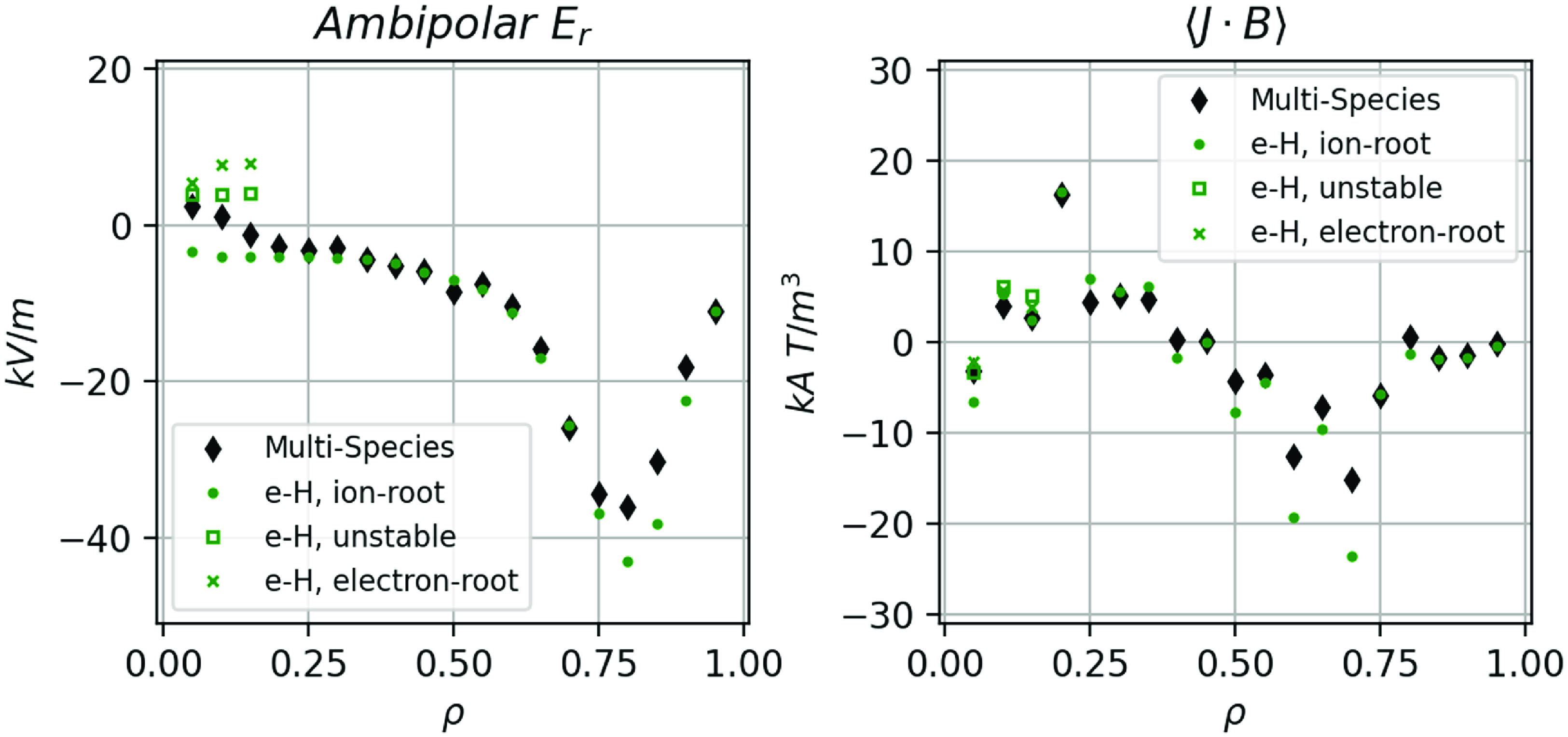
Figure 11. On the left, the ambipolar radial electric field $E_r$
for two-species electron-hydrogen (green) and multi-species (black) plasmas are plotted as a function of
$E_r$
for two-species electron-hydrogen (green) and multi-species (black) plasmas are plotted as a function of $\rho$
using the profiles of figure 4. The corresponding bootstrap current profile for the associated cases are plotted on the right. The stable ion-root solution is used to calculate the bootstrap current profile.
$\rho$
using the profiles of figure 4. The corresponding bootstrap current profile for the associated cases are plotted on the right. The stable ion-root solution is used to calculate the bootstrap current profile.
The only envisioned external sources required for Infinity Two operation are pellet injection and electron cyclotron resonance heating (ECRH). In the confinement studies described in the following section, we use ECRH heating assuming the availability of $236$
GHz gyrotrons with fundamental resonance at
$236$
GHz gyrotrons with fundamental resonance at $8. 42$
T (Jelonnek et al. Reference Jelonnek2017; Thumm et al. Reference Thumm, Denisov, Sakamoto and Tran2019). The density cutoff for
$8. 42$
T (Jelonnek et al. Reference Jelonnek2017; Thumm et al. Reference Thumm, Denisov, Sakamoto and Tran2019). The density cutoff for $O1$
is
$O1$
is $\sim 7 \times 10^{20}$
m
$\sim 7 \times 10^{20}$
m $^{-3}$
which is higher than the envisioned operating densities. Perpendicular launch is assumed to minimize current drive. The targeted operating scenario (
$^{-3}$
which is higher than the envisioned operating densities. Perpendicular launch is assumed to minimize current drive. The targeted operating scenario ( $800$
MW DT fusion,
$800$
MW DT fusion, $Q = 40$
) requires
$Q = 40$
) requires $20$
MW of ECRH in steady state, however, start-up scenarios may require slightly elevated values of ECRH power (Guttenfelder et al. Reference Guttenfelder2025). With high central electron temperatures, very high first pass absorption is expected with widths of order a few cm. As such, when modeling the ECRH source, a Gaussian profile centered at
$20$
MW of ECRH in steady state, however, start-up scenarios may require slightly elevated values of ECRH power (Guttenfelder et al. Reference Guttenfelder2025). With high central electron temperatures, very high first pass absorption is expected with widths of order a few cm. As such, when modeling the ECRH source, a Gaussian profile centered at $\rho = 0.1$
and width
$\rho = 0.1$
and width $\sigma = 0.05$
is used.
$\sigma = 0.05$
is used.
For the plasma performance projections, a fixed density profile is assumed. In order to assess the viability of this assumption, a fueling profile is computed using pellet mass ablation model (Parks & Turnbull Reference Parks and Turnbull1978; Zhang et al. Reference Zhang, McClenaghan, Parks, Lau and Wu2022; McClenaghan et al. Reference McClenaghan, Lao, Parks, Wu, Zhang and Chan2023). In particular, we employ the model from these works to compute the mass ablation rate $G$
in units of
$G$
in units of $g s^{-1}$
using
$g s^{-1}$
using
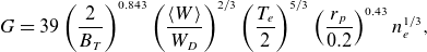 \begin{equation} G = 39 \left(\frac {2}{B_T}\right)^{0.843} \left(\frac {\langle W\rangle }{W_D}\right)^{2/3} \left(\frac {T_e}{2}\right)^{5/3} \left(\frac {r_p}{0.2}\right)^{0.43} n_e^{1/3}, \end{equation}
where the mean molar mass $\langle W \rangle$
is taken as the weighted average of the molar masses of deuterium
$\langle W \rangle$
is taken as the weighted average of the molar masses of deuterium $W_D$
and tritium and
$W_D$
and tritium and $B_T$
,
$B_T$
, $T_e$
,
$T_e$
, $r_p$
and
$r_p$
and $n_e$
have units or T, keV, cm and
$n_e$
have units or T, keV, cm and $10^{20}$
m
$10^{20}$
m $^{-3}$
, respectively.
$^{-3}$
, respectively.
5. Plasma performance projections
The configuration described in the previous section, Infinity Two, is assessed using a suite of computational tools in the areas of MHD stability, energetic ion confinement and turbulent and neoclassical transport.
5.1. Magentohydrodynamic stability
The MHD stability properties of stellarators, in many ways, are rather different than that of other magnetic confinement systems. The MHD instability boundaries generally provide rigorous bounds for plasma operation in other confinement systems including the tokamak. Stellarators have operated at high $\langle \beta \rangle$
and have tested predictions of pressure-induced MHD instability boundaries (Okamura et al. Reference Okamura1999; Watanabe et al. Reference Watanabe2005; Nakajima et al. Reference Nakajima, Hudson, Hegna and Nakamura2006; Geiger et al. Reference Geiger2017; Sato et al. Reference Sato, Nakajima, Watanabe and Todo2017). Typically, when linear ideal MHD stability boundaries to long-wavelength instability are breached, magnetic fluctuations are observed. However, abrupt termination of the discharge is largely avoided with MHD activity providing weak confinement degradation (Weller et al. Reference Weller2009). While not detrimental to stellarator operation, it is still desirable to avoid operation with MHD instabilities to ensure optimal confinement.
$\langle \beta \rangle$
and have tested predictions of pressure-induced MHD instability boundaries (Okamura et al. Reference Okamura1999; Watanabe et al. Reference Watanabe2005; Nakajima et al. Reference Nakajima, Hudson, Hegna and Nakamura2006; Geiger et al. Reference Geiger2017; Sato et al. Reference Sato, Nakajima, Watanabe and Todo2017). Typically, when linear ideal MHD stability boundaries to long-wavelength instability are breached, magnetic fluctuations are observed. However, abrupt termination of the discharge is largely avoided with MHD activity providing weak confinement degradation (Weller et al. Reference Weller2009). While not detrimental to stellarator operation, it is still desirable to avoid operation with MHD instabilities to ensure optimal confinement.
A conventional metric of ideal MHD stability in stellarators is provided by the Mercier criterion as described in (A3), which is a measure of local interchange instability. As shown in figure 12, the configuration is Mercier stable over the bulk of the confinement region for the base case $\langle \beta \rangle = 1.6\,\%$
. As the configuration has small averaged magnetic shear and small net current, the components
$\langle \beta \rangle = 1.6\,\%$
. As the configuration has small averaged magnetic shear and small net current, the components $D_s$
and
$D_s$
and $D_V$
do not contribute significantly to the Mercier criterion. Rather, the two dominant components are provided by the magnetic well (
$D_V$
do not contribute significantly to the Mercier criterion. Rather, the two dominant components are provided by the magnetic well ( $D_W$
) and a contribution accounting for Pfirsch–Schluter currents due to geodesic curvature and the non-circularity of the flux surfaces (
$D_W$
) and a contribution accounting for Pfirsch–Schluter currents due to geodesic curvature and the non-circularity of the flux surfaces ( $g^{ss}$
) denoted (
$g^{ss}$
) denoted ( $D_G$
). As shown in the right panel of figure 12, the configuration has a magnetic well throughout the volume, but violates Mercier stability outside of
$D_G$
). As shown in the right panel of figure 12, the configuration has a magnetic well throughout the volume, but violates Mercier stability outside of $\rho \gt 0.97$
due to the unfavorable stability properties of
$\rho \gt 0.97$
due to the unfavorable stability properties of $D_G$
. In principle, this may lead to ideal (or resistive) interchange instabilities. However, as
$D_G$
. In principle, this may lead to ideal (or resistive) interchange instabilities. However, as $D_G$
scales as
$D_G$
scales as $({\rm d}p/{\rm d}s)^2$
and
$({\rm d}p/{\rm d}s)^2$
and $D_W$
scales as
$D_W$
scales as $({\rm d}p/{\rm d}s)$
, interchange stability will be recovered with a slight reduction in pressure gradient in the outer radii. As shown in the left panel of figure 12, calculations at higher
$({\rm d}p/{\rm d}s)$
, interchange stability will be recovered with a slight reduction in pressure gradient in the outer radii. As shown in the left panel of figure 12, calculations at higher $\langle \beta \rangle$
with the same plasma profile shape show a deepening of the magnetic well at large radii and the region of Mercier stability growing with
$\langle \beta \rangle$
with the same plasma profile shape show a deepening of the magnetic well at large radii and the region of Mercier stability growing with $\langle \beta \rangle$
.
$\langle \beta \rangle$
.
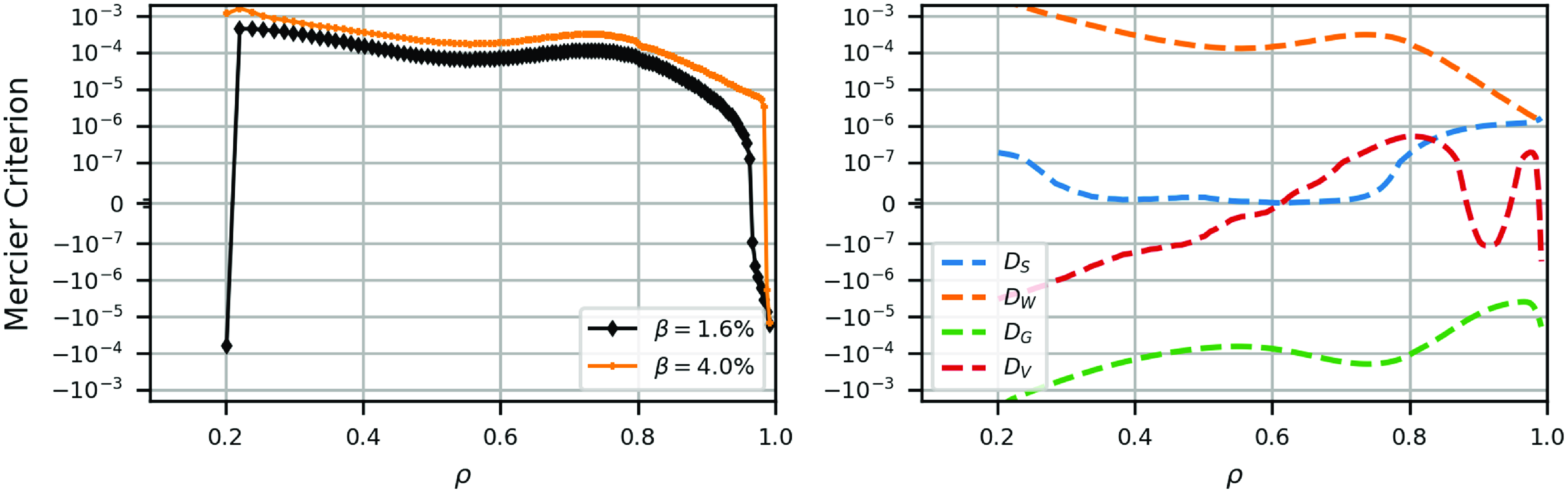
Figure 12. The Mercier stability criterion is plotted as a function of $\rho$
for the base configuration at
$\rho$
for the base configuration at $\langle \beta \rangle = 1.6\,\%$
and at an elevated
$\langle \beta \rangle = 1.6\,\%$
and at an elevated $\langle \beta \rangle = 4.0\,\%$
. The free and fixed boundary VMEC equilibria provide the same stability prediction to high accuracy. In the right panel, the four components of the Mercier criteria (as defined in Appendix A) are plotted as a function of
$\langle \beta \rangle = 4.0\,\%$
. The free and fixed boundary VMEC equilibria provide the same stability prediction to high accuracy. In the right panel, the four components of the Mercier criteria (as defined in Appendix A) are plotted as a function of $\rho$
of the base configuration.
$\rho$
of the base configuration.
To address the ideal MHD stability boundaries of the configuration, a sequence of VMEC equilibria are constructed which all retain the same pressure profile shape but vary the overall amplitude of the pressure and associated bootstrap current. Ideal ballooning stability can be then assessed for the equilibria set using the COBRAVMEC code on a selection of magnetic surfaces. As shown in figure 13, the base configuration is stable to ideal ballooning at the $\langle \beta \rangle = 1.6\,\%$
operating point, but can violate ballooning stability when
$\langle \beta \rangle = 1.6\,\%$
operating point, but can violate ballooning stability when $\langle \beta \rangle \gt 2\,\%$
. In this situation, instability onset occurs first near
$\langle \beta \rangle \gt 2\,\%$
. In this situation, instability onset occurs first near $\rho \sim 0.7$
. In practice, however, this should not be viewed as a
$\rho \sim 0.7$
. In practice, however, this should not be viewed as a $\langle \beta \rangle$
limit of the configuration. At high operating
$\langle \beta \rangle$
limit of the configuration. At high operating $\langle \beta \rangle$
, KBMs emerge in the turbulent transport simulations which have the effect of lowering the gradients in the vicinity of the ideal ballooning stability boundary. Hence, a consequence of operating near MHD ballooning stability limits is confinement degradation. If the profiles found in the self-consistent transport modeling described in § 5.3 are used for the
$\langle \beta \rangle$
, KBMs emerge in the turbulent transport simulations which have the effect of lowering the gradients in the vicinity of the ideal ballooning stability boundary. Hence, a consequence of operating near MHD ballooning stability limits is confinement degradation. If the profiles found in the self-consistent transport modeling described in § 5.3 are used for the $\langle \beta \rangle$
scan instead of the model profiles, the ideal ballooning onset occurs at
$\langle \beta \rangle$
scan instead of the model profiles, the ideal ballooning onset occurs at $\langle \beta \rangle = 2.7\,\%$
. Indeed, the self-consistent transport modeling has the effect of reducing the transport sufficiently at the trouble spots (
$\langle \beta \rangle = 2.7\,\%$
. Indeed, the self-consistent transport modeling has the effect of reducing the transport sufficiently at the trouble spots ( $\rho \sim 0.7$
) to alleviate the strong ballooning drive of those locations. In figure 13, we also plot the results if one uses the analytically prescribed profile
$\rho \sim 0.7$
) to alleviate the strong ballooning drive of those locations. In figure 13, we also plot the results if one uses the analytically prescribed profile $p = p_0(1 - \rho ^2)$
, as this parabolic profile has been used elsewhere in the literature. Evidently, the parabolic profile leads to more optimistic estimates for the ballooning beta limit compared with the profiles based on transport calculations. For both the parabolic profile and T3D profiles, the location of the most unstable ballooning modes occur at outer radii
$p = p_0(1 - \rho ^2)$
, as this parabolic profile has been used elsewhere in the literature. Evidently, the parabolic profile leads to more optimistic estimates for the ballooning beta limit compared with the profiles based on transport calculations. For both the parabolic profile and T3D profiles, the location of the most unstable ballooning modes occur at outer radii $0.9 \leqslant \rho \leqslant 1.0$
.
$0.9 \leqslant \rho \leqslant 1.0$
.
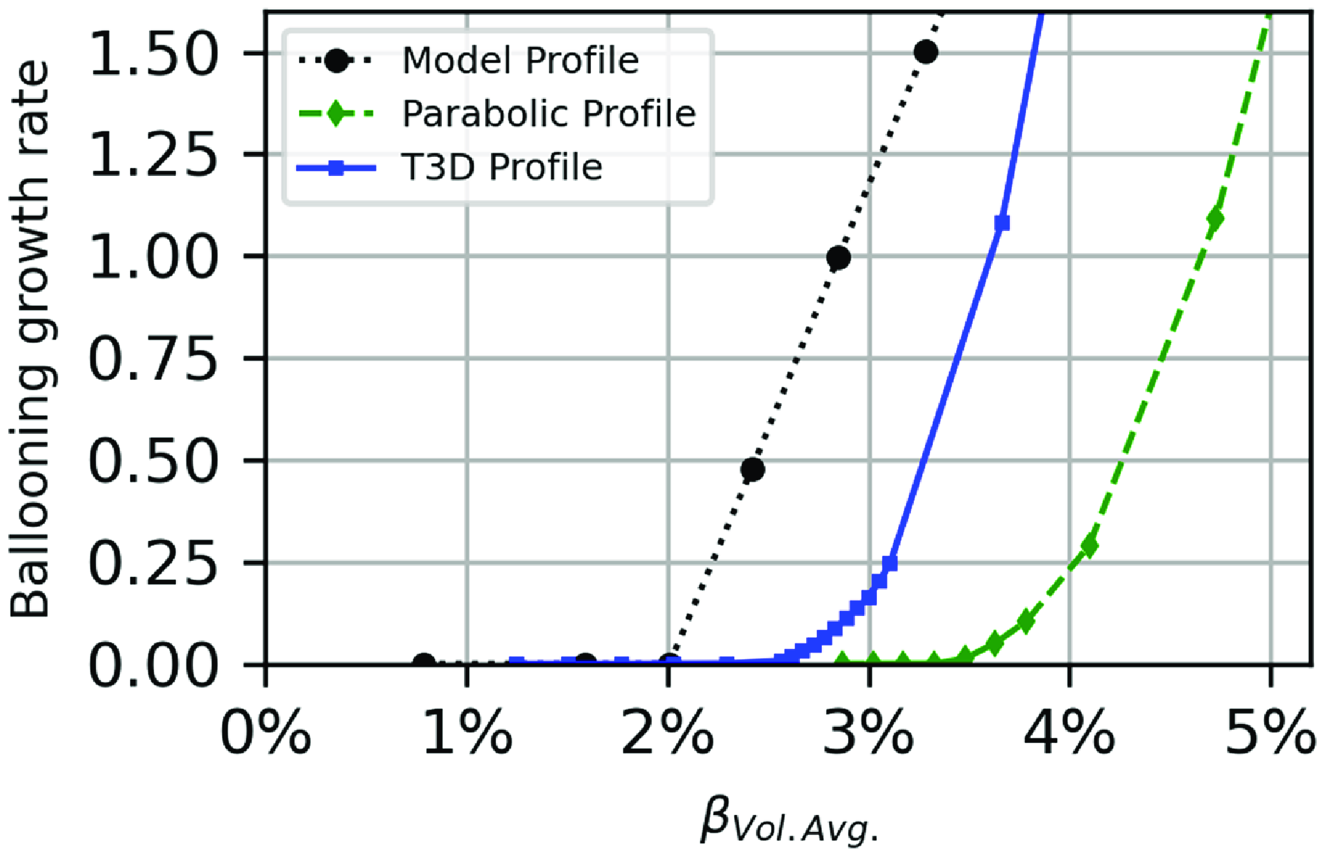
Figure 13. Growth rates of the most unstable ideal MHD ballooning mode (maximized over flux surface and field line labels) as a function of volume-averaged $\langle \beta \rangle$
for three profiles. The circles correspond to the profiles of figure 4, the boxes correspond to those computed in the T3D-GX-SFINCS profiles of figure 20 and the diamonds correspond to the analytic profile
$\langle \beta \rangle$
for three profiles. The circles correspond to the profiles of figure 4, the boxes correspond to those computed in the T3D-GX-SFINCS profiles of figure 20 and the diamonds correspond to the analytic profile $p = p_0(1 - \rho ^2)$
.
$p = p_0(1 - \rho ^2)$
.
The same set of VMEC equilibria used in the $\langle \beta \rangle$
scan for ballooning stability is used to assess the global MHD stability properties of the configuration using the TERPSICHORE code. A key difference between the stability properties of stellarators relative to axisymmetric configurations involves the Fourier mode selection for the linear eigenmode. For stellarators with field period
$\langle \beta \rangle$
scan for ballooning stability is used to assess the global MHD stability properties of the configuration using the TERPSICHORE code. A key difference between the stability properties of stellarators relative to axisymmetric configurations involves the Fourier mode selection for the linear eigenmode. For stellarators with field period $N$
, Fourier harmonics with toroidal mode number
$N$
, Fourier harmonics with toroidal mode number $n$
are coupled to all other Fourier harmonics with
$n$
are coupled to all other Fourier harmonics with $n + kN$
for integer values of
$n + kN$
for integer values of $k$
. For
$k$
. For $N = 4$
, there are three families of eigenmodes. Results from the
$N = 4$
, there are three families of eigenmodes. Results from the $\langle \beta \rangle$
scan are shown in figure 14, where the ideal MHD eigenvalue (
$\langle \beta \rangle$
scan are shown in figure 14, where the ideal MHD eigenvalue ( $-\lambda \sim \gamma ^2$
) is plotted as a function of
$-\lambda \sim \gamma ^2$
) is plotted as a function of $\langle \beta \rangle$
. The three curves correspond to the three classes of MHD instabilities, ones that preserve the stellarator symmetry of the equilibrium and two that break the symmetry via
$\langle \beta \rangle$
. The three curves correspond to the three classes of MHD instabilities, ones that preserve the stellarator symmetry of the equilibrium and two that break the symmetry via $n =$
odd or even toroidal mode numbers. Here, global modes are considered with dominant toroidal mode numbers satisfying
$n =$
odd or even toroidal mode numbers. Here, global modes are considered with dominant toroidal mode numbers satisfying $n \lt 15$
. Vigorous instabilities with large extended eigenmodes (as shown on the right panel of figure 14) do not appear until reaching
$n \lt 15$
. Vigorous instabilities with large extended eigenmodes (as shown on the right panel of figure 14) do not appear until reaching $\langle \beta \rangle \gt 3.2\,\%$
. The eigenmode shape for the most unstable mode at
$\langle \beta \rangle \gt 3.2\,\%$
. The eigenmode shape for the most unstable mode at $\langle \beta \rangle = 3.72\,\%$
is dominated by the Fourier harmonics with
$\langle \beta \rangle = 3.72\,\%$
is dominated by the Fourier harmonics with $m = 16, n = 11$
. The primary instability is in the
$m = 16, n = 11$
. The primary instability is in the $n = 1$
mode family and is dominantly driven by the pressure/curvature drive with little contribution from the parallel current.
$n = 1$
mode family and is dominantly driven by the pressure/curvature drive with little contribution from the parallel current.
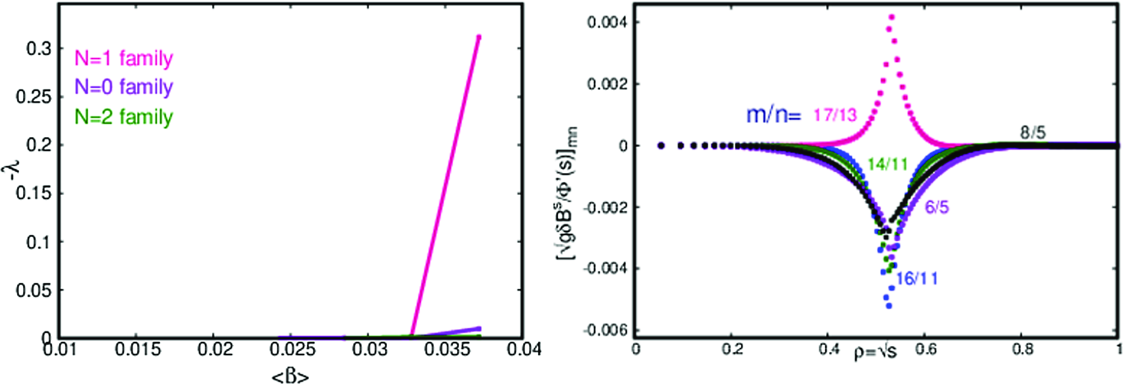
Figure 14. Global MHD instability calculations are performed on a set of MHD equilibria with different volume-averaged $\langle \beta \rangle$
. For each case, three different families of MHD instabilities are tested corresponding to those that preserve stellarator symmetry, and those that break symmetry through the addition of
$\langle \beta \rangle$
. For each case, three different families of MHD instabilities are tested corresponding to those that preserve stellarator symmetry, and those that break symmetry through the addition of $n = 1$
and
$n = 1$
and $n = 2$
(and helically coupled) harmonics. The right plot shows the eigenmode structure of the most unstable mode for
$n = 2$
(and helically coupled) harmonics. The right plot shows the eigenmode structure of the most unstable mode for $\langle \beta \rangle = 3.72\,\%$
.
$\langle \beta \rangle = 3.72\,\%$
.
5.2. Energetic particle physics
Energetic ion physics is a critical issue for stellarator physics design and is a primary driver for the stellarator optimization strategy. Due to the low collisionality and wide orbits of high energy particles (e.g. alpha particles in a DT reactor), it is particularly challenging to confine the trajectories of energetic ions with 3-D magnetic fields. Additionally, due to their high energy densities, large velocities and non-thermal distribution functions, energetic particles can drive instabilities through wave–particle resonant interactions with Alfvénic modes. As the plasmas addressed in this study use a strategy of avoiding MHD instabilities in the base operation, we do not address the question of the interaction of alpha particles with global MHD instabilities.
To address the concern of energetic particle losses due to unconfined particle orbits, we use the ASCOT5 code (Särkimäki Reference Särkimäki2019) to model the alpha-particle and energy losses. These simulations follow guiding-center (GC) or full-orbit (FO) 3.5 MeV alpha particles initialized in space following the Bosch–Hale fusion reactivity (Bosch & Hale Reference Bosch and Hale1992) applied to the thermal plasma profiles. Coulomb collisions between alpha particles and the background electrons, deuterium, tritium and an assumed 5 % He ash impurity are included in these simulations. For these Monte-Carlo calculations, an initial spatial and velocity distribution of fusion borne alpha particles is employed. Subsequent GC or FO simulations are then used to quantify energy and particle loss rates to the first wall as well as quantifying the power loads as a function of location on the wall. The device wall in these simulations is generated by computing a conformal envelope of the plasma that includes the magnetic island divertor region outside the plasma volume. The average distance between the wall and the island separatrix is roughly $10$
cm. During the course of this study, different wall locations were chosen (created by varying the distance between the wall and the last closed flux surface) (Carbajal et al. Reference Carbajal2025). The energy and particle loss rates are relatively insensitive to the wall choice.
$10$
cm. During the course of this study, different wall locations were chosen (created by varying the distance between the wall and the last closed flux surface) (Carbajal et al. Reference Carbajal2025). The energy and particle loss rates are relatively insensitive to the wall choice.
A simple measure of the effectiveness of a magnetic field’s ability to confine energetic particles is by calculations using collisionless guiding-center orbtis (Bader et al. Reference Bader, Drevlak, Anderson, Faber, Hegna, Likin, Schmitt and Talmadge2019). Collisionless GC calculations for $3.5$
MeV alpha particles following the initialization procedure described previously show small alpha losses (
$3.5$
MeV alpha particles following the initialization procedure described previously show small alpha losses ( $\sim 0.5 \,\%$
). All of the lost collisionless orbits are due to deeply trapped particles driven by slight mismatches of the
$\sim 0.5 \,\%$
). All of the lost collisionless orbits are due to deeply trapped particles driven by slight mismatches of the $B_{min}$
values on each surface. However, more accurate quantitative predictions require the inclusion of Coulomb collision effects and full ion orbits. Under these more realistic conditions, alpha-particle energy losses are larger than the collisionless GC estimate.
$B_{min}$
values on each surface. However, more accurate quantitative predictions require the inclusion of Coulomb collision effects and full ion orbits. Under these more realistic conditions, alpha-particle energy losses are larger than the collisionless GC estimate.
Simulations of alpha particles produced in Infinity Two at $800$
MW DT fusion are performed that include both collisions and full ion orbits. In this scenario, simulations show less than 5 % particle losses and less than 1.5 % of energy losses to the wall. In figure 15, we show the distribution functions of energy and simulated time of GC alpha particles in an ASCOT5 simulation. In the right panel, a running count of when the alpha particle is either lost to the wall (in blue) or thermalizes with the background plasma (in red) is provided as a function of time. In the left panel, a plot of the alpha particle’s energy at the time it is lost is recorded in blue and a distribution of the confined alpha particles at the end of the simulation in red. We observed that for the alpha particles that are lost, the losses occur within a few tens of milliseconds, while still carrying relatively high energies,
$800$
MW DT fusion are performed that include both collisions and full ion orbits. In this scenario, simulations show less than 5 % particle losses and less than 1.5 % of energy losses to the wall. In figure 15, we show the distribution functions of energy and simulated time of GC alpha particles in an ASCOT5 simulation. In the right panel, a running count of when the alpha particle is either lost to the wall (in blue) or thermalizes with the background plasma (in red) is provided as a function of time. In the left panel, a plot of the alpha particle’s energy at the time it is lost is recorded in blue and a distribution of the confined alpha particles at the end of the simulation in red. We observed that for the alpha particles that are lost, the losses occur within a few tens of milliseconds, while still carrying relatively high energies, $\mathcal {E}\geqslant 100$
keV. The bulk of the alpha particles become thermalized in the core plasma, visible in the peak of
$\mathcal {E}\geqslant 100$
keV. The bulk of the alpha particles become thermalized in the core plasma, visible in the peak of $f_\alpha (\mathcal {E})$
at
$f_\alpha (\mathcal {E})$
at $\mathcal {E}\sim 10$
keV, with a small fraction of lost alphas being thermalized at the scrape-off-layer (SOL) before they reach the wall, apparent in the peak of
$\mathcal {E}\sim 10$
keV, with a small fraction of lost alphas being thermalized at the scrape-off-layer (SOL) before they reach the wall, apparent in the peak of $f_\alpha (\mathcal {E})$
at
$f_\alpha (\mathcal {E})$
at $\mathcal {E}\sim 100$
eV. Here, the SOL is modeled as a region with constant density
$\mathcal {E}\sim 100$
eV. Here, the SOL is modeled as a region with constant density $n_{e,SOL} = 6 \times 10^{-19}$
m
$n_{e,SOL} = 6 \times 10^{-19}$
m $^{-3}$
and temperature
$^{-3}$
and temperature $T_{e,SOL} = T_{i,SOL} = 100$
eV.
$T_{e,SOL} = T_{i,SOL} = 100$
eV.
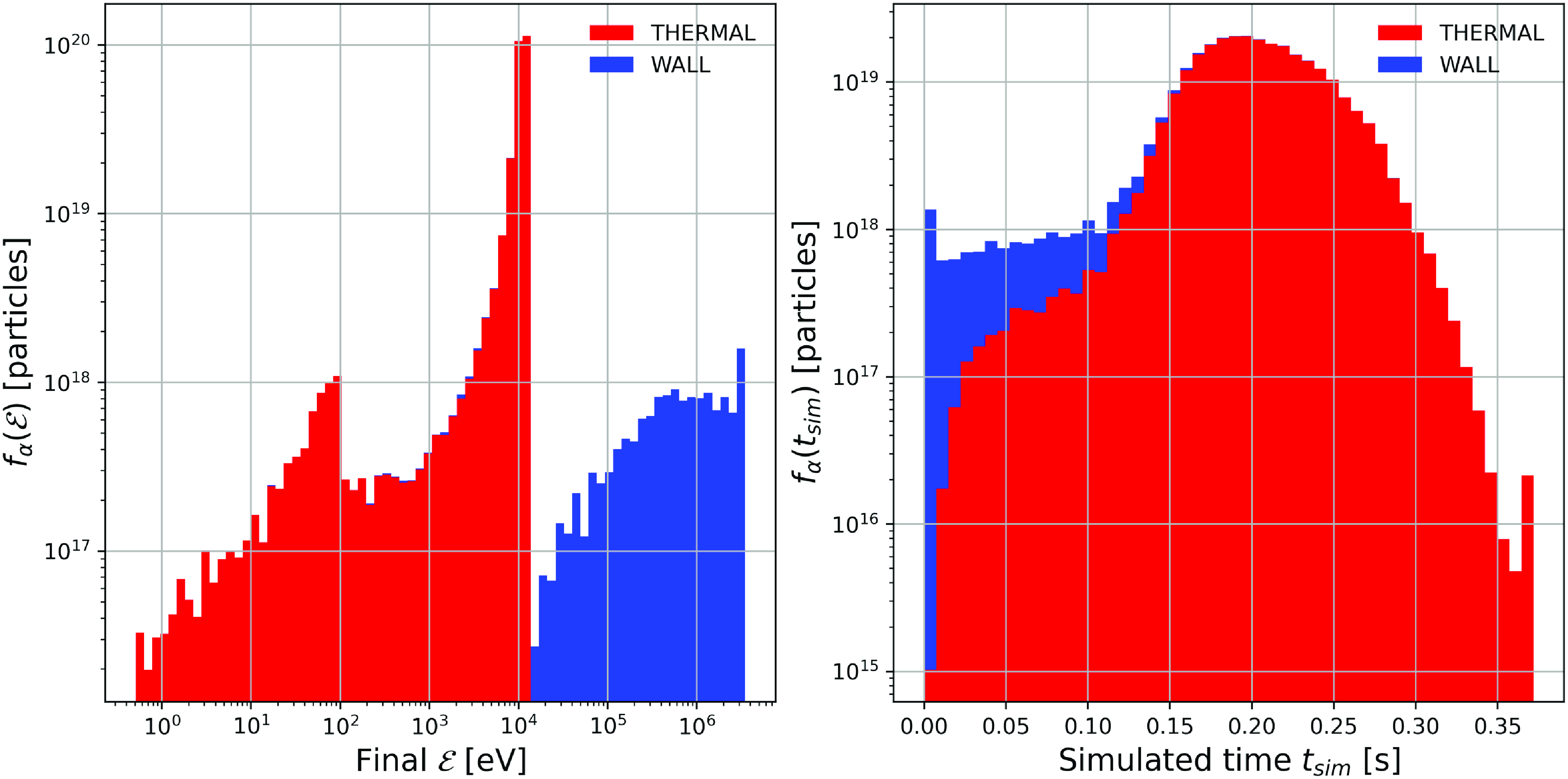
Figure 15. Distribution functions of energy (left) and simulated time (right) GC alpha particles in ASCOT5 simulations of Infinity Two.
The dominant losses are due to deeply trapped particles as shown in figure 16. In this figure, we classify lost GC alpha particles based on their initial value of $B_{mirror}$
. Here,
$B_{mirror}$
. Here, $B_{mirror}$
is the magnitude of the magnetic field at which particles are expected to be reflected (bounce),
$B_{mirror}$
is the magnitude of the magnetic field at which particles are expected to be reflected (bounce), $B_{mirror} = \mathcal {E}_0/\mu$
, where
$B_{mirror} = \mathcal {E}_0/\mu$
, where $\mathcal {E}_0$
is the initial (birth) energy of alpha-particles at 3.5 MeV, and
$\mathcal {E}_0$
is the initial (birth) energy of alpha-particles at 3.5 MeV, and $\mu$
their initial magnetic moment. Trapped particles satisfy the property
$\mu$
their initial magnetic moment. Trapped particles satisfy the property $B_{min} \lt B_{mirror} \lt B_{max}$
where
$B_{min} \lt B_{mirror} \lt B_{max}$
where $B_{min}$
(
$B_{min}$
( $B_{max}$
) is the minimum (maximum) value of
$B_{max}$
) is the minimum (maximum) value of $|B|$
on the birth magnetic surface of the alpha particle. In figure 16, the vertical magenta lines denote these values for
$|B|$
on the birth magnetic surface of the alpha particle. In figure 16, the vertical magenta lines denote these values for $\rho = 0.5$
. Because collisions do not conserve energy and magnetic moment, particles that start on confined orbits, such as passing particles can be lost. However, these are lost after many collisions and thus long time scales. All lost particles prior to 10 ms arise from the deeply trapped orbits.
$\rho = 0.5$
. Because collisions do not conserve energy and magnetic moment, particles that start on confined orbits, such as passing particles can be lost. However, these are lost after many collisions and thus long time scales. All lost particles prior to 10 ms arise from the deeply trapped orbits.
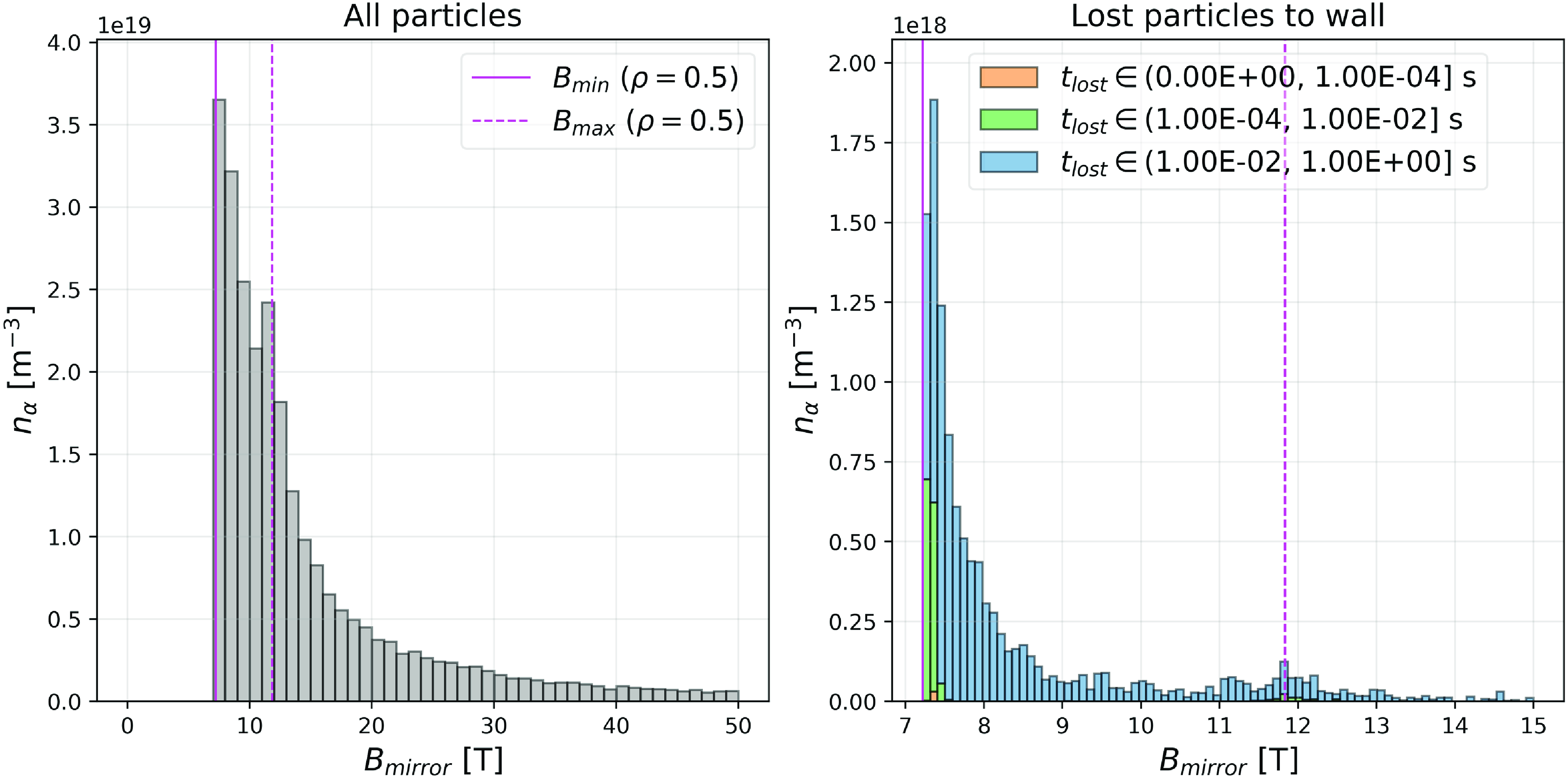
Figure 16. On the left, orbit classification of simulated collisional GC alpha particles. Particles with $B_{min} \lt B_{mirror} \lt B_{max}$
on a flux surface are trapped particles. On right, lost particles as a function of initial
$B_{min} \lt B_{mirror} \lt B_{max}$
on a flux surface are trapped particles. On right, lost particles as a function of initial $B_{mirror}$
.
$B_{mirror}$
.
In figure 17, we plot the spatial distribution of power loads due to lost alpha particles. Simulation results indicate localized hot spots with peak values of 2.5 MW/m $^2$
. These hot spots tend to correlate with the X-points of the island separatrix. Heat loads from these simulations show the four-field-period periodicity of Infinity Two to within a few percent accuracy.
$^2$
. These hot spots tend to correlate with the X-points of the island separatrix. Heat loads from these simulations show the four-field-period periodicity of Infinity Two to within a few percent accuracy.
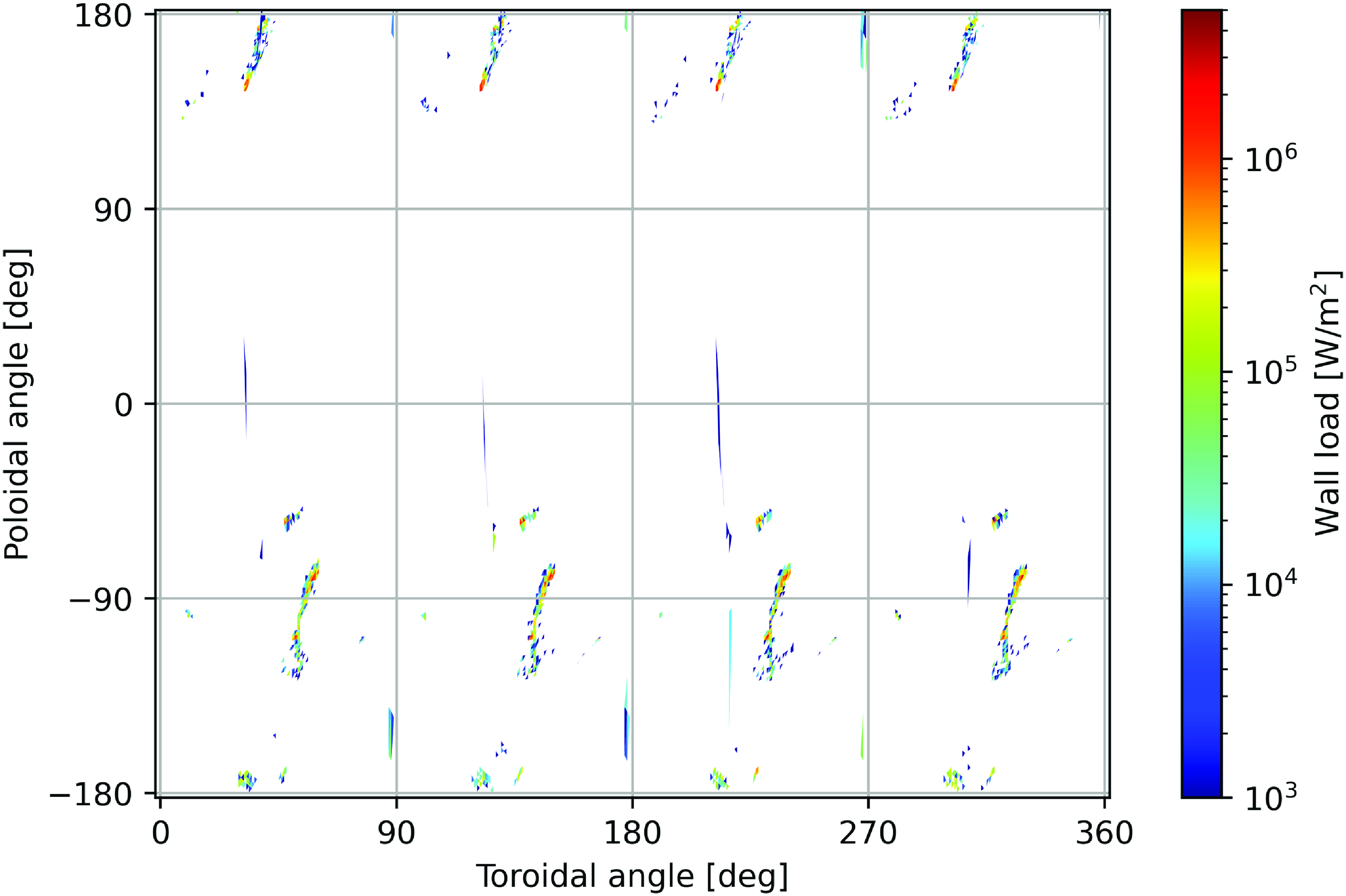
Figure 17. Heat loads due to lost alpha particles.
The characteristic properties of the Alfvén eigenmode (AE) spectrum are defined by the flatness of the density profile in the core region and the small global magnetic shear ( ${\rm d}{{\iota\kern-1pt\!\mbox{-}\kern0.5pt}}/{\rm d}\rho$
) throughout the configuration. Because of these properties, broad gaps in all AE families are present. As such, continuum damping plays a relatively small role in determining AE stability, with the alpha-particle
${\rm d}{{\iota\kern-1pt\!\mbox{-}\kern0.5pt}}/{\rm d}\rho$
) throughout the configuration. Because of these properties, broad gaps in all AE families are present. As such, continuum damping plays a relatively small role in determining AE stability, with the alpha-particle $\langle \beta \rangle$
, resonance intensity and electron-ion Landau and radiative damping playing a more central role.
$\langle \beta \rangle$
, resonance intensity and electron-ion Landau and radiative damping playing a more central role.
The stability analysis of AEs using the STELLGAP (Spong et al. Reference Spong, D’Azevedo and Todo2010) and FAR3d codes (Rodriguez et al. Reference Rodriguez, Spong, Garcia, Ghai and Ortiz2024) shows all of the modes are stable at the base operating conditions $\langle \beta \rangle = 1.6 \,\%$
. Largely, this is a consequence of the high-field, high density approach of Infinity Two which leads to a relatively low value of
$\langle \beta \rangle = 1.6 \,\%$
. Largely, this is a consequence of the high-field, high density approach of Infinity Two which leads to a relatively low value of $\langle \beta \rangle _{\alpha } = 0.31\,\%$
. At yet higher operating densities, there is the expectation that the AEs remain stable as increased ion densities decreases both the alpha-particle
$\langle \beta \rangle _{\alpha } = 0.31\,\%$
. At yet higher operating densities, there is the expectation that the AEs remain stable as increased ion densities decreases both the alpha-particle $\langle \beta \rangle$
drive (due to smaller slowing down times) and the waveparticle resonance between the alpha partcles and the Alfvénic waves.
$\langle \beta \rangle$
drive (due to smaller slowing down times) and the waveparticle resonance between the alpha partcles and the Alfvénic waves.
5.3. Turbulent transport and confinement physics
The confinement challenge for a stellarator fusion reactor is to stably maintain high core plasma temperatures ( $T \sim 10$
keV) at sufficiently high density in order to ensure large DT fusion reactivity. These requirements must be consistent with associated fueling and particle transport that enables the required confinement while avoiding the retention of fusion ash. The confinement solution also needs to be compatible with an exhaust system that effectively performs the needed particle and power handling using a high-Z impurity-induced radiative mantle. Moreover, the confinement scheme must also avoid the accumulation of these high-Z impurities in the plasma core.
$T \sim 10$
keV) at sufficiently high density in order to ensure large DT fusion reactivity. These requirements must be consistent with associated fueling and particle transport that enables the required confinement while avoiding the retention of fusion ash. The confinement solution also needs to be compatible with an exhaust system that effectively performs the needed particle and power handling using a high-Z impurity-induced radiative mantle. Moreover, the confinement scheme must also avoid the accumulation of these high-Z impurities in the plasma core.
At this point, it is worth reflecting on the optimization strategy employed and its implications for the confinement physics. One important goal is to minimize the level of neoclassical transport throughout the plasma confinement region. As shown in figure 9, the neoclassical transport coefficient satisfies $\epsilon _{eff} \lt 0.004$
throughout the confinement volume and attains
$\epsilon _{eff} \lt 0.004$
throughout the confinement volume and attains $\epsilon _{eff} \sim 0.001$
in the deep core.
$\epsilon _{eff} \sim 0.001$
in the deep core.
With the successful reduction of neoclassical transport using optimization, turbulent transport due to drift-wave microinstabilities is the dominant loss mechanism in modern day optimized stellarators. The most dangerous microinstabilities tend to be ITG instabilities, TEMs and KBMs. Each of these instabilities are described by the gyrokinetic model. For our configuration, we model the turbulent transport using nonlinear flux-tube calculations with the GX gyrokinetic code. For this work, electromagnetic non-adiabatic electron simulations with fusion-relevant plasma $\langle \beta \rangle$
and collisionality are required to provide the most realistic projections to turbulent transport in a burning plasma environment. The T3D-GX-SFINCS transport framework is employed to predict the plasma profiles consistent with nonlinear gyrokinetic predictions of the turbulent transport, neoclassical transport, self-consistent heating profiles from DT fusion, radiation physics and particle and heating sources.
$\langle \beta \rangle$
and collisionality are required to provide the most realistic projections to turbulent transport in a burning plasma environment. The T3D-GX-SFINCS transport framework is employed to predict the plasma profiles consistent with nonlinear gyrokinetic predictions of the turbulent transport, neoclassical transport, self-consistent heating profiles from DT fusion, radiation physics and particle and heating sources.
The ITG-induced turbulent transport consistently plays an important role in most toroidal confinement devices and has been a particularly vexing problem for W7-X (Beurskens et al. Reference Beurskens2021). As such, optimizing for reduced ITG turbulence has been an emphasis. This is achieved through a combination of 3-D shaping and appealing to enhanced density gradient in the confinement region. With the absence of density gradients in the core, ITG driven turbulence tends to dominate in this region. Noting the discussion introduced following (2.8), we typically find the ion temperature is set by the critical gradient for ITG excitation in the core. However, at larger radii, the larger density gradient is known to be strongly stabilizing to ITG. Hence, large ITGs can be supported there.
Simply peaking the density gradient in and of itself is not sufficient to guarantee reduced turbulent transport. At higher density gradient, the non-adiabatic electron response becomes important as well. In particular, TEM instabilities may also play a more prominent role. However, for Infinity Two, we appeal to the max- $J$
property as part of the optimization approach. In particular this has a beneficial effect on reducing TEM instabilities through the impact of the shaping on the precessional drift properties of the trapped electrons (Connor et al. Reference Connor, Hastie and Martin1983; Hegna Reference Hegna2015; Mackenbach et al. Reference Mackenbach, Duff, Gerard, Proll, Helander and Hegna2023).
$J$
property as part of the optimization approach. In particular this has a beneficial effect on reducing TEM instabilities through the impact of the shaping on the precessional drift properties of the trapped electrons (Connor et al. Reference Connor, Hastie and Martin1983; Hegna Reference Hegna2015; Mackenbach et al. Reference Mackenbach, Duff, Gerard, Proll, Helander and Hegna2023).
The high-field strategy of Infinity Two also alleviates the impact of KBMs. Avoidance of ballooning instability in the confinement region is an important operational constraint. Moreover, the use of the high-field, low- $\langle \beta \rangle$
approach allows fusion-relevant conditions at relatively high density and low temperature consistent with Sudo density limits. Additionally, the presence of an edge pedestal region is not required nor desired as this allows the penetration of continuous pellets in the confinement region enabling the primary mechanism for controlling ITG turbulence via density peaking.
$\langle \beta \rangle$
approach allows fusion-relevant conditions at relatively high density and low temperature consistent with Sudo density limits. Additionally, the presence of an edge pedestal region is not required nor desired as this allows the penetration of continuous pellets in the confinement region enabling the primary mechanism for controlling ITG turbulence via density peaking.
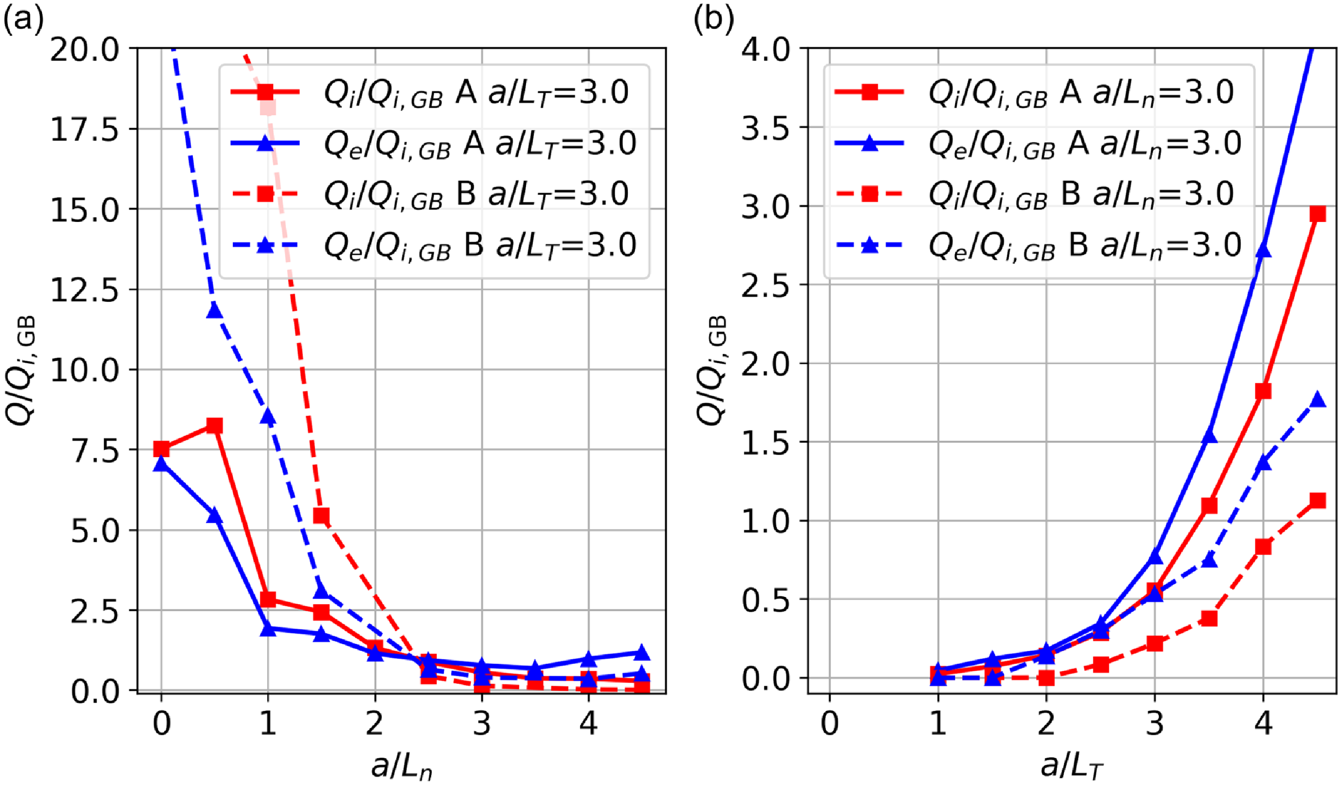
Figure 18. In the left panel, the electron (blue) and ion (red) normalized heat fluxes as a function of $a/L_n$
at fixed
$a/L_n$
at fixed $a/L_{T_i} = a/L_{T_e} = 3.0$
for two different stellarator configurations. The solid lines correspond to the Infinity Two configuration (a) described in § 4. The other configuration(b) is an
$a/L_{T_i} = a/L_{T_e} = 3.0$
for two different stellarator configurations. The solid lines correspond to the Infinity Two configuration (a) described in § 4. The other configuration(b) is an $A = 7$
QI alternative design from the Type One Energy database. In the right panel, the ion (red) and electron (blue) normalized heat fluxes are plotted as a function of
$A = 7$
QI alternative design from the Type One Energy database. In the right panel, the ion (red) and electron (blue) normalized heat fluxes are plotted as a function of $a/L_{T_i} = a/L_{T_e}$
at fixed
$a/L_{T_i} = a/L_{T_e}$
at fixed $a/L_n = 3.0$
for both cases, the equilibrium surface corresponds to
$a/L_n = 3.0$
for both cases, the equilibrium surface corresponds to $\rho = 0.7$
.
$\rho = 0.7$
.
Many of the desired design features are consistent with results reported here. To demonstrate the reduction of turbulent transport in the confinement region with elevated density gradient, standalone flux-tube gyrokinetic simulations are performed. In figure 18, nonlinear GX simulations show turbulent transport predictions at $\rho = 0.7$
for two configurations at
$\rho = 0.7$
for two configurations at $\langle \beta \rangle = 2.0\,\%$
. Here,
$\langle \beta \rangle = 2.0\,\%$
. Here, $a/L_n = - (a/n_e) {\rm d}n_e/{\rm d}\rho$
,
$a/L_n = - (a/n_e) {\rm d}n_e/{\rm d}\rho$
, $a/L_{T_i} = - (a/T_i) {\rm d}T_i/{\rm d}\rho$
and
$a/L_{T_i} = - (a/T_i) {\rm d}T_i/{\rm d}\rho$
and $a/L_{T_e} = - (a/T_e) {\rm d}T_e/{\rm d}\rho$
. The heat flux predictions are reported in gyro-Bohm units where
$a/L_{T_e} = - (a/T_e) {\rm d}T_e/{\rm d}\rho$
. The heat flux predictions are reported in gyro-Bohm units where $Q_{i,GB} = (\rho _i/a)^2 nv_{T_i} T_i$
,
$Q_{i,GB} = (\rho _i/a)^2 nv_{T_i} T_i$
, $v_{T_i} = \sqrt {T_i/m_i}$
, and
$v_{T_i} = \sqrt {T_i/m_i}$
, and $\rho _i = m_iv_{T_i}/(Z_i e B)$
. In the left panel, the electron (blue) and ion (red) normalized heat fluxes are plotted as a function
$\rho _i = m_iv_{T_i}/(Z_i e B)$
. In the left panel, the electron (blue) and ion (red) normalized heat fluxes are plotted as a function $a/L_n$
at fixed
$a/L_n$
at fixed $a/L_{T_i} = a/L_{T_i}= 3$
. The solid lines correspond to the Infinity Two configuration (labeled A) discussed throughout this paper. The dotted lines correspond to an
$a/L_{T_i} = a/L_{T_i}= 3$
. The solid lines correspond to the Infinity Two configuration (labeled A) discussed throughout this paper. The dotted lines correspond to an $A = 7, N = 4$
alternative QI configuration (labeled B) from the Type One Energy dataset. As shown on the left, both configurations demonstrate reduced heat flux at high density gradient with
$A = 7, N = 4$
alternative QI configuration (labeled B) from the Type One Energy dataset. As shown on the left, both configurations demonstrate reduced heat flux at high density gradient with $Q_i/Q_{i,GB} \lt 1$
for both configurations for
$Q_i/Q_{i,GB} \lt 1$
for both configurations for $a/L_n \gt 2$
. Indeed, a number of stellarator configurations (particularly QI) demonstrate similar improved turbulent transport properties at elevated density gradient (Sánchez et al. Reference Sánchez, Velasco, Calvo and Mulas2023; Thienpondt et al. Reference Thienpondt2023; Goodman et al. Reference Goodman, Xanthopoulos, Plunk, Smith, Nührenberg, Beidler, Henneberg, Roberg-Clark, Drevlak and Helander2024). The right plot provides predictions of normalized heat flux at fixed
$a/L_n \gt 2$
. Indeed, a number of stellarator configurations (particularly QI) demonstrate similar improved turbulent transport properties at elevated density gradient (Sánchez et al. Reference Sánchez, Velasco, Calvo and Mulas2023; Thienpondt et al. Reference Thienpondt2023; Goodman et al. Reference Goodman, Xanthopoulos, Plunk, Smith, Nührenberg, Beidler, Henneberg, Roberg-Clark, Drevlak and Helander2024). The right plot provides predictions of normalized heat flux at fixed $a/L_n = 3.0$
as a function of
$a/L_n = 3.0$
as a function of $a/L_T = a/L_{T_i} = a/L_{T_e}$
. Notably, configuration B tends to outperform Infinity Two by roughly a factor of two at elevated density gradient. However, other aspects of this configuration were not as desirable as the configuration chosen for Infinity Two. Nonetheless, the existence of configuration B indicates that there is still further room to accommodate better turbulent transport optimization in the stellarator FPP.
$a/L_T = a/L_{T_i} = a/L_{T_e}$
. Notably, configuration B tends to outperform Infinity Two by roughly a factor of two at elevated density gradient. However, other aspects of this configuration were not as desirable as the configuration chosen for Infinity Two. Nonetheless, the existence of configuration B indicates that there is still further room to accommodate better turbulent transport optimization in the stellarator FPP.
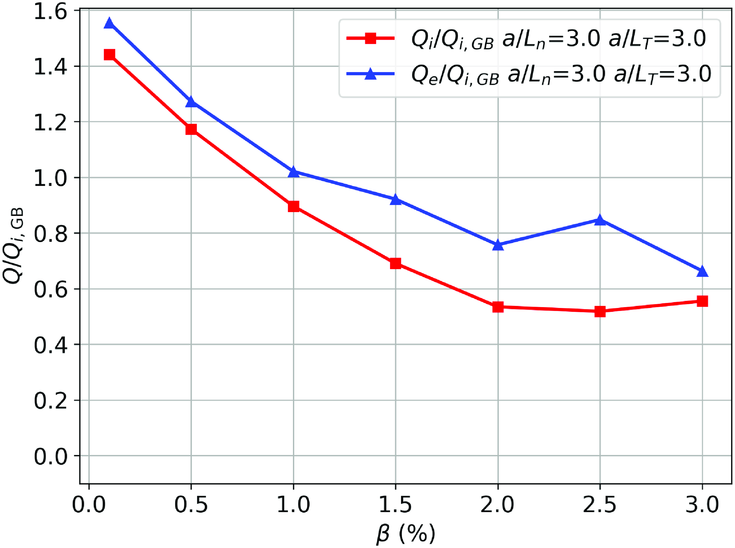
Figure 19. Electron (blue) and ion (red) normalized heat fluxes as a functions of $\beta$
with
$\beta$
with $a/L_{n} = a/L_{T_e} = a/L_{T_i} = 3.0$
at
$a/L_{n} = a/L_{T_e} = a/L_{T_i} = 3.0$
at $\rho = 0.7$
of Infinity Two.
$\rho = 0.7$
of Infinity Two.
Figure 19 shows predictions for Infinity Two’s turbulent transport as a function of $\beta (\rho = 0.7)$
. The nonlinear gyrokinetic simulations use
$\beta (\rho = 0.7)$
. The nonlinear gyrokinetic simulations use $a/L_n = a/L_{Te} = 1/L_{T_i} = 3.0$
at the
$a/L_n = a/L_{Te} = 1/L_{T_i} = 3.0$
at the $\rho = 0. 7$
surface. These results show a general decrease in turbulent transport with
$\rho = 0. 7$
surface. These results show a general decrease in turbulent transport with $\beta$
as would be expected for ITG-dominant transport. There is a slight increase in electron heat transport at elevated
$\beta$
as would be expected for ITG-dominant transport. There is a slight increase in electron heat transport at elevated $\beta$
due to a magnetic flutter contribution at higher wavenumbers (
$\beta$
due to a magnetic flutter contribution at higher wavenumbers ( $k_y \rho \sim 0.6\!-\!1.0$
) than the dominant turbulent transport wavenumbers. A likley cause for this uptick is described in linear gyrokinetic simulations which show the presence of electromagnetic modes at
$k_y \rho \sim 0.6\!-\!1.0$
) than the dominant turbulent transport wavenumbers. A likley cause for this uptick is described in linear gyrokinetic simulations which show the presence of electromagnetic modes at $k_y\rho _i \sim 0.6\!-\!1.0$
with tearing parity propagating in the electron drift direction. Notably, the simulations results suggests no signs of sub-critical KBM turbulence (McKinney et al. Reference McKinney, Pueschel, Faber, Hegna, Ishizawa and Terry2021; Mulholland et al. Reference Mulholland, Aleynikova, Faber, Pueschel, Proll, Hegna, Terry and Nührenberg2023, Reference Mulholland, Pueschel, Proll, Aleynikova, Faber, Terry, Hegna and Nührenberg2025) for these cases. However, virulent KBM turbulent transport is predicted when nearing the ideal MHD ballooning stability boundary.
$k_y\rho _i \sim 0.6\!-\!1.0$
with tearing parity propagating in the electron drift direction. Notably, the simulations results suggests no signs of sub-critical KBM turbulence (McKinney et al. Reference McKinney, Pueschel, Faber, Hegna, Ishizawa and Terry2021; Mulholland et al. Reference Mulholland, Aleynikova, Faber, Pueschel, Proll, Hegna, Terry and Nührenberg2023, Reference Mulholland, Pueschel, Proll, Aleynikova, Faber, Terry, Hegna and Nührenberg2025) for these cases. However, virulent KBM turbulent transport is predicted when nearing the ideal MHD ballooning stability boundary.
While the gyrokinetic analysis demonstrates favorable transport properties for Infinity Two, transport-based predictions are required to quantitatively obtain DT fusion performance based on realistic profiles consistent with fueling, auxiliary heating (if needed) and the transport properties. For this task, we use the T3D-GX-SFINCS transport framework to self-consistently construct the profiles consistent with high-fidelity neoclassical and nonlinear gyrokinetic turbulence predictions. In these calculations, fusion alpha heating, collisional energy exchange and radiation losses (bremsstrahlung, line, recombination, synchrotron) are accounted for in the energy balance. A 50-50 deuterium-tritium fuel mix is assumed with fuel dilution factor $f_{DT} = (n_D + n_T)/n_e = 0.85$
and helium concentration
$f_{DT} = (n_D + n_T)/n_e = 0.85$
and helium concentration $f_{He} = 0.05$
used in the simulations. Also included in the simulations are a small tungsten concentration (
$f_{He} = 0.05$
used in the simulations. Also included in the simulations are a small tungsten concentration ( $f_{W} = 1.5 \times 10^{-5}$
) owing to the likely first wall material in Infinity Two and a small amount of a low-
$f_{W} = 1.5 \times 10^{-5}$
) owing to the likely first wall material in Infinity Two and a small amount of a low- $Z$
material which is modeled as neon
$Z$
material which is modeled as neon $f_{Ne} = 4.9 \times 10^{-3}$
. This results in an effective charge
$f_{Ne} = 4.9 \times 10^{-3}$
. This results in an effective charge $Z_{eff} = 1.62$
, assumed constant across the volume.
$Z_{eff} = 1.62$
, assumed constant across the volume.
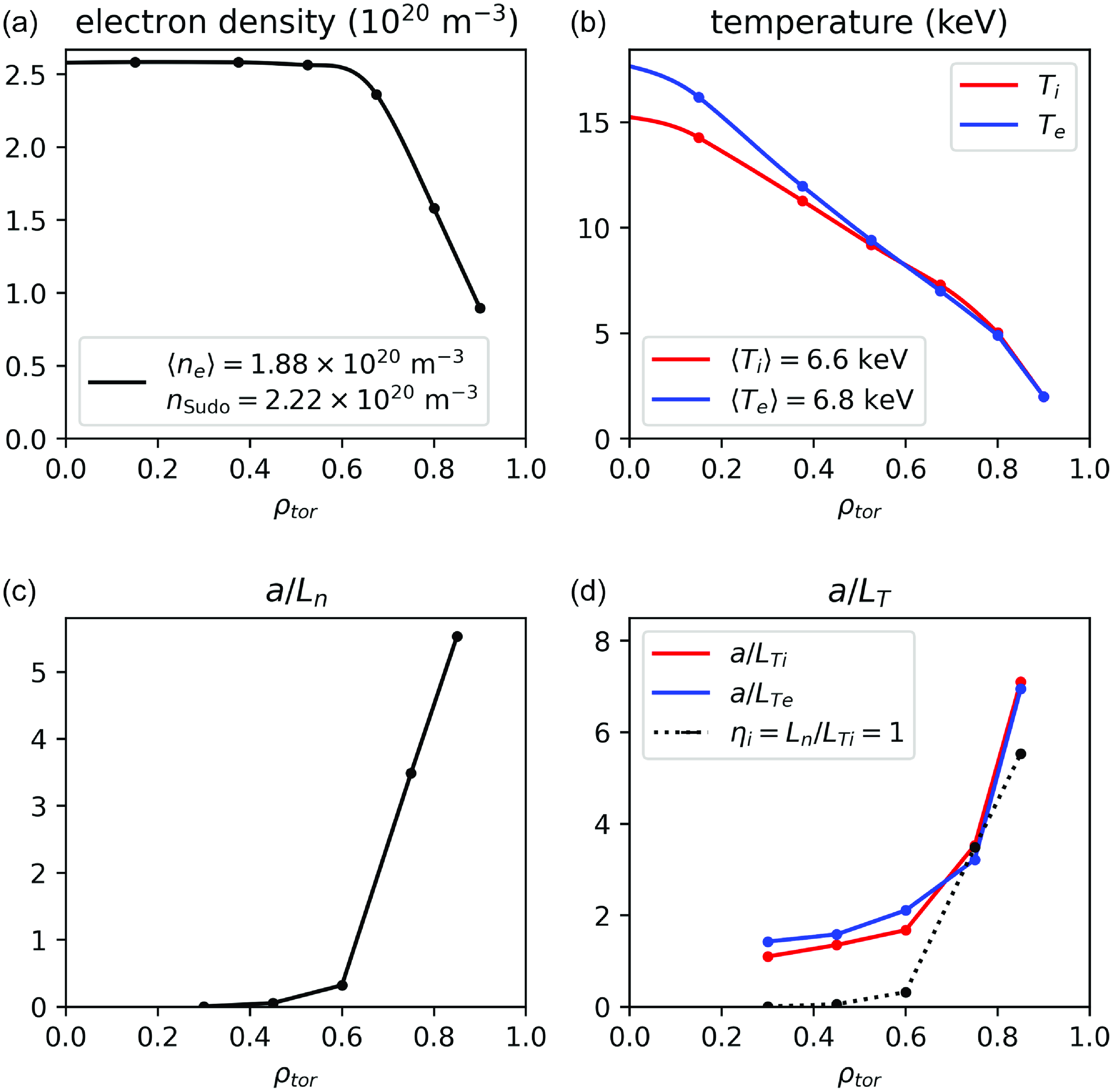
Figure 20. T3D-GX-SFINCS predictions of the baseline operating scenario with $800$
MW DT fusion power and
$800$
MW DT fusion power and $20$
MW auxiliary heating (
$20$
MW auxiliary heating ( $Q=40$
). Temperature profile predictions are shown in (b) with the assumed density profile in (a), along with density (c) and temperature (d) normalized inverse gradient scale lengths.
$Q=40$
). Temperature profile predictions are shown in (b) with the assumed density profile in (a), along with density (c) and temperature (d) normalized inverse gradient scale lengths.
T3D-GX-SFINCS calculations have been performed for several cases, as detailed in Guttenfelder et al. (Reference Guttenfelder2025). Here, we report the results for one of these simulations, the baseline case producing 800 MW of DT fusion power with fusion gain $Q=40$
. Figure 20 shows the results of the T3D-GX-SFINCS simulation predicting the temperature profiles of Infinity Two for an operating point with an assumed (fixed) density profile consistent with pellet fueling assumptions with volume-averaged density
$Q=40$
. Figure 20 shows the results of the T3D-GX-SFINCS simulation predicting the temperature profiles of Infinity Two for an operating point with an assumed (fixed) density profile consistent with pellet fueling assumptions with volume-averaged density $\langle n_e \rangle = 1.88\times 10^{20}$
m
$\langle n_e \rangle = 1.88\times 10^{20}$
m $^{-3}$
. For this simulation, a
$^{-3}$
. For this simulation, a $90\,\%$
alpha heating efficiency is assumed to account for alpha losses before thermalization (this estimate is likely conservative as our energetic particle calculations show greater than
$90\,\%$
alpha heating efficiency is assumed to account for alpha losses before thermalization (this estimate is likely conservative as our energetic particle calculations show greater than $98\,\%$
efficiency). The gyrokinetic simulations embedded in the transport calculations are performed at realistic values of plasma beta (
$98\,\%$
efficiency). The gyrokinetic simulations embedded in the transport calculations are performed at realistic values of plasma beta ( $\langle \beta \rangle \sim 1.5\,\%$
), fully electromagnetically with collisions. The transport simulation requires a boundary condition on the plasma temperature. For the simulation of figure 20,
$\langle \beta \rangle \sim 1.5\,\%$
), fully electromagnetically with collisions. The transport simulation requires a boundary condition on the plasma temperature. For the simulation of figure 20, $T_e(\rho = 0.9) = T_i(\rho = 0.9) = 2$
keV is employed. At the moment, there is no easy way to predict the choice of the boundary condition with any precision. As such, we recognize there is some uncertainty in how to make definitive projections and this will be the subject of further study. At these density levels, radiation losses (primarily bremsstrahlung) are an important loss channel, leading to a core radiative fraction of
$T_e(\rho = 0.9) = T_i(\rho = 0.9) = 2$
keV is employed. At the moment, there is no easy way to predict the choice of the boundary condition with any precision. As such, we recognize there is some uncertainty in how to make definitive projections and this will be the subject of further study. At these density levels, radiation losses (primarily bremsstrahlung) are an important loss channel, leading to a core radiative fraction of $f_{{rad}} = P_{{rad}}/(P_{\alpha }+P_{aux}) = 0.41$
. However, the volume-averaged density satisfies
$f_{{rad}} = P_{{rad}}/(P_{\alpha }+P_{aux}) = 0.41$
. However, the volume-averaged density satisfies $\langle n_e\rangle /n_{{Sudo}} \approx 0.92$
with edge density
$\langle n_e\rangle /n_{{Sudo}} \approx 0.92$
with edge density $n_{{edge}}\sim 0.4 n_{{Sudo}}$
, well below the Sudo value (Miyazawa et al. Reference Miyazawa2008). As discussed in § 5.1, with the more realistic plasma profiles, ideal ballooning modes are stable at these values of
$n_{{edge}}\sim 0.4 n_{{Sudo}}$
, well below the Sudo value (Miyazawa et al. Reference Miyazawa2008). As discussed in § 5.1, with the more realistic plasma profiles, ideal ballooning modes are stable at these values of $\langle \beta \rangle$
. Indeed, there are no indications that KBM turbulence plays a substantial role in turbulent transport in these conditions.
$\langle \beta \rangle$
. Indeed, there are no indications that KBM turbulence plays a substantial role in turbulent transport in these conditions.
These high-fidelity transport simulations use coupling to nonlinear gyrokinetic (GX) and neoclassical (SFINCS) solvers to compute transport fluxes, which are then used to evolve the pressure profile until a steady state is reached that satisfies power balance. The resulting steady-state power balance is shown in figure 21(a), with total fluxes (solid lines with open circles) matching the integrated power sources (dashed lines with closed circles) in each radius. Separate transport flux contributions from turbulence (diamonds) and neoclassical transport (squares) are shown for both DT ions and electrons. The neoclassical transport is more than an order of magnitude lower than the turbulent transport across the entire plasma cross-section in both ion and electron channels. This is an indication of successful neoclassical optimization, such that turbulence is the dominant loss mechanism. Analysis shows that core region ( $\rho \sim 0.3$
) is dominated by ITG turbulence as would be expected with weak stabilizing density gradient. In the larger density region (
$\rho \sim 0.3$
) is dominated by ITG turbulence as would be expected with weak stabilizing density gradient. In the larger density region ( $\rho \sim 0.6\!-\!0.9$
), a notable TEM signature is present that contributes to electron transport. Additionally, smaller electron flutter transport at high wavenumber (
$\rho \sim 0.6\!-\!0.9$
), a notable TEM signature is present that contributes to electron transport. Additionally, smaller electron flutter transport at high wavenumber ( $k_y\rho _i \sim 0.6\!-\!1.0$
) is also present. A more comprehensive discussion of the turbulence properties of these plasmas is discussed in the accompanying paper by (Guttenfelder et al. Reference Guttenfelder2025).
$k_y\rho _i \sim 0.6\!-\!1.0$
) is also present. A more comprehensive discussion of the turbulence properties of these plasmas is discussed in the accompanying paper by (Guttenfelder et al. Reference Guttenfelder2025).
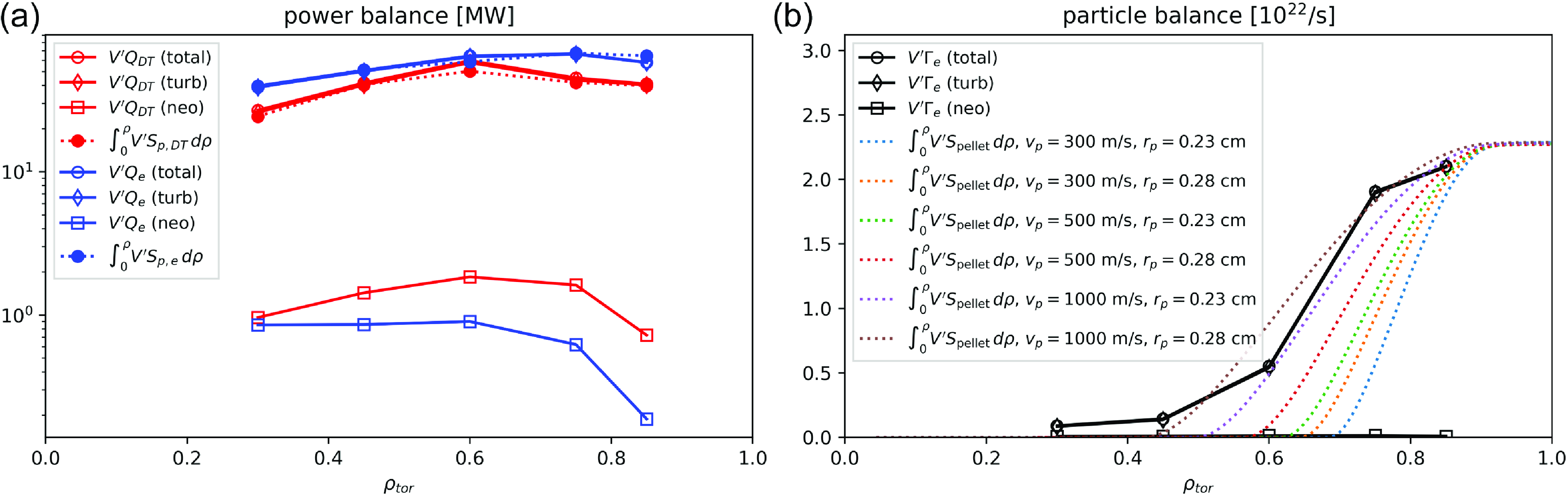
Figure 21. (a) Power balance for the baseline $800$
MW operating scenario, with electrons (blue) and bulk DT ions (red). Solid lines with open markers denote turbulent (diamonds), neoclassical (squares) and total (circles) fluxes times the differential volume
$800$
MW operating scenario, with electrons (blue) and bulk DT ions (red). Solid lines with open markers denote turbulent (diamonds), neoclassical (squares) and total (circles) fluxes times the differential volume $V'$
in MW. The volume integrated sources are shown with dotted lines with closed circle markers. (b) An assessment of particle balance is performed by comparing particle fluxes calculated from transport calculations (open circles) with integrated pellet source profiles with various assumptions for pellet radius (
$V'$
in MW. The volume integrated sources are shown with dotted lines with closed circle markers. (b) An assessment of particle balance is performed by comparing particle fluxes calculated from transport calculations (open circles) with integrated pellet source profiles with various assumptions for pellet radius ( $r_p$
) and pellet velocity (
$r_p$
) and pellet velocity ( $v_p$
).
$v_p$
).
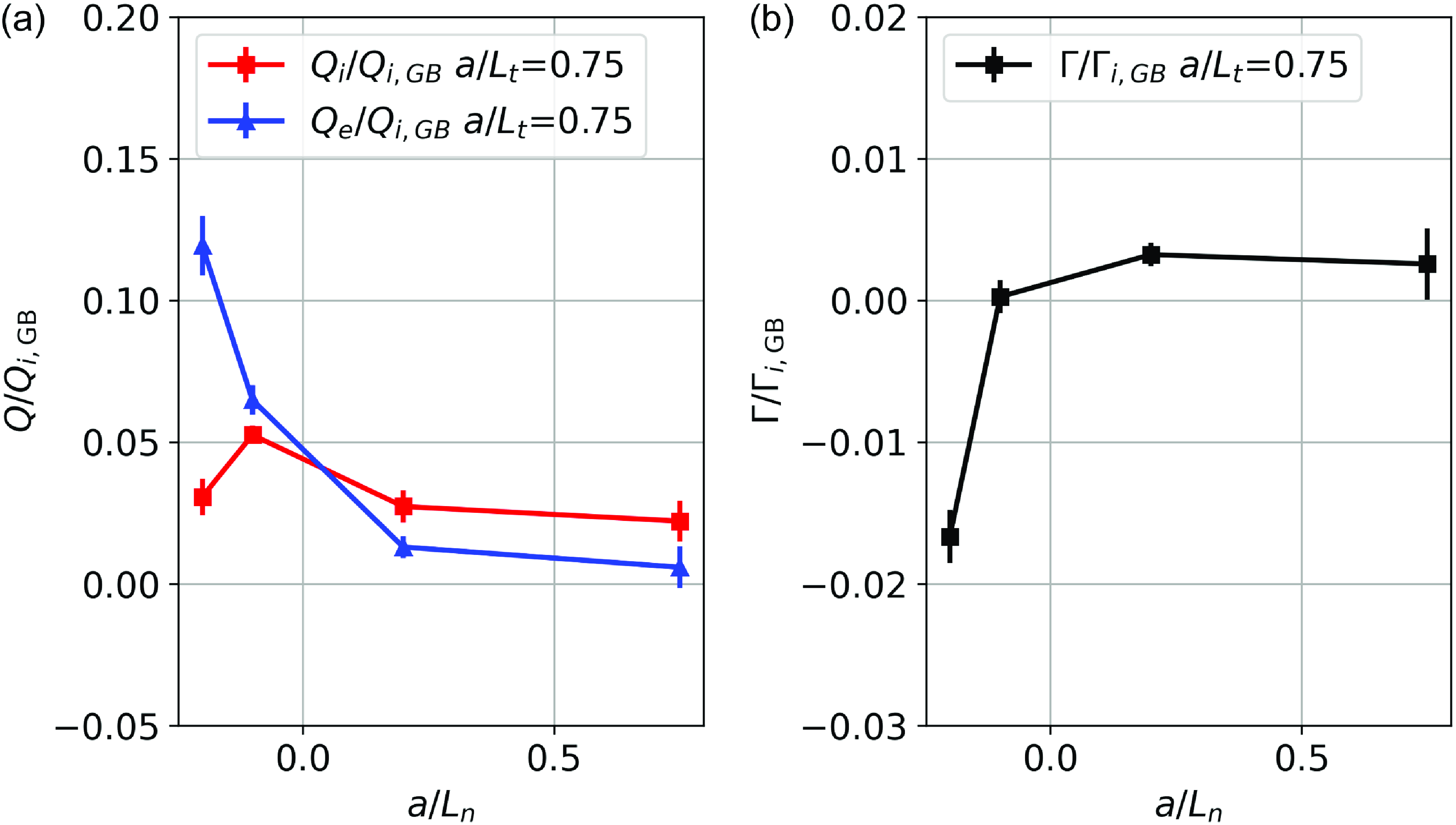
Figure 22. (a) Electron (blue) and ion (red) heat flux and (b) particle flux as a function of density gradient ( $a/L_n$
) at
$a/L_n$
) at $\rho = 0.3$
with fixed
$\rho = 0.3$
with fixed $a/L_{T_e} = a/L_{T_i} = 0.75$
.
$a/L_{T_e} = a/L_{T_i} = 0.75$
.
In figure 21(b) the particle flux due to neoclassical and turbulent transport calculations are provided using the assumed density profile. This is compared with the integrated pellet source profiles from the pellet model of McClenaghan et al. Reference McClenaghan, Lao, Parks, Wu, Zhang and Chan(2023) with various assumptions for the particle radius ( $r_p$
) and velocity
$r_p$
) and velocity $v_p$
. The analysis shows that the assumed density shape can be produced with
$v_p$
. The analysis shows that the assumed density shape can be produced with $v_p \sim 1000\,\rm ms^-{^1}$
.
$v_p \sim 1000\,\rm ms^-{^1}$
.
In the core region, predicted particle fluxes consistent with the assumed density profile and computed temperature profiles show a very small but outward component. This raises the possibility that hollow density profiles may be a natural outcome of the core turbulent transport properties. To assess this possibility, a set of nonlinear simulations are performed while scanning $a/L_n$
at
$a/L_n$
at $\rho = 0.3$
with fixed
$\rho = 0.3$
with fixed $a/L_{T_e} = a/L_{T_i} = 0.75$
. The results of this scan are shown in figure 22, which show very litte density hollowing (
$a/L_{T_e} = a/L_{T_i} = 0.75$
. The results of this scan are shown in figure 22, which show very litte density hollowing ( $-0.2 \lt a/L_n \lt 0$
) is required to match the zero particle flux condition (
$-0.2 \lt a/L_n \lt 0$
) is required to match the zero particle flux condition ( $\unicode{x1D6E4} = 0)$
.
$\unicode{x1D6E4} = 0)$
.
Figure 23 shows particle fluxes from additional standalone turbulence and neoclassical calculations that include helium ash, tungsten and neon impurity species, assuming impurity density profiles proportional to the electron density profile with concentrations $(f_{{He}}, f_{{W}}, f_{{Ne}})=(0.05, 1.5\times 10^{-5}, 4.9\times 10^{-3})$
. These results indicate that turbulence also dominates neoclassical transport of impurities, producing strong net outward transport near the periphery despite the presence of a small neoclassical impurity pinch. These computational results largely mirror those observed in W7-X which indicate ambient ITG turbulence is large enough to prevent impurity accumulation in standard operation (Langenberg et al. Reference Langenberg2020).
$(f_{{He}}, f_{{W}}, f_{{Ne}})=(0.05, 1.5\times 10^{-5}, 4.9\times 10^{-3})$
. These results indicate that turbulence also dominates neoclassical transport of impurities, producing strong net outward transport near the periphery despite the presence of a small neoclassical impurity pinch. These computational results largely mirror those observed in W7-X which indicate ambient ITG turbulence is large enough to prevent impurity accumulation in standard operation (Langenberg et al. Reference Langenberg2020).
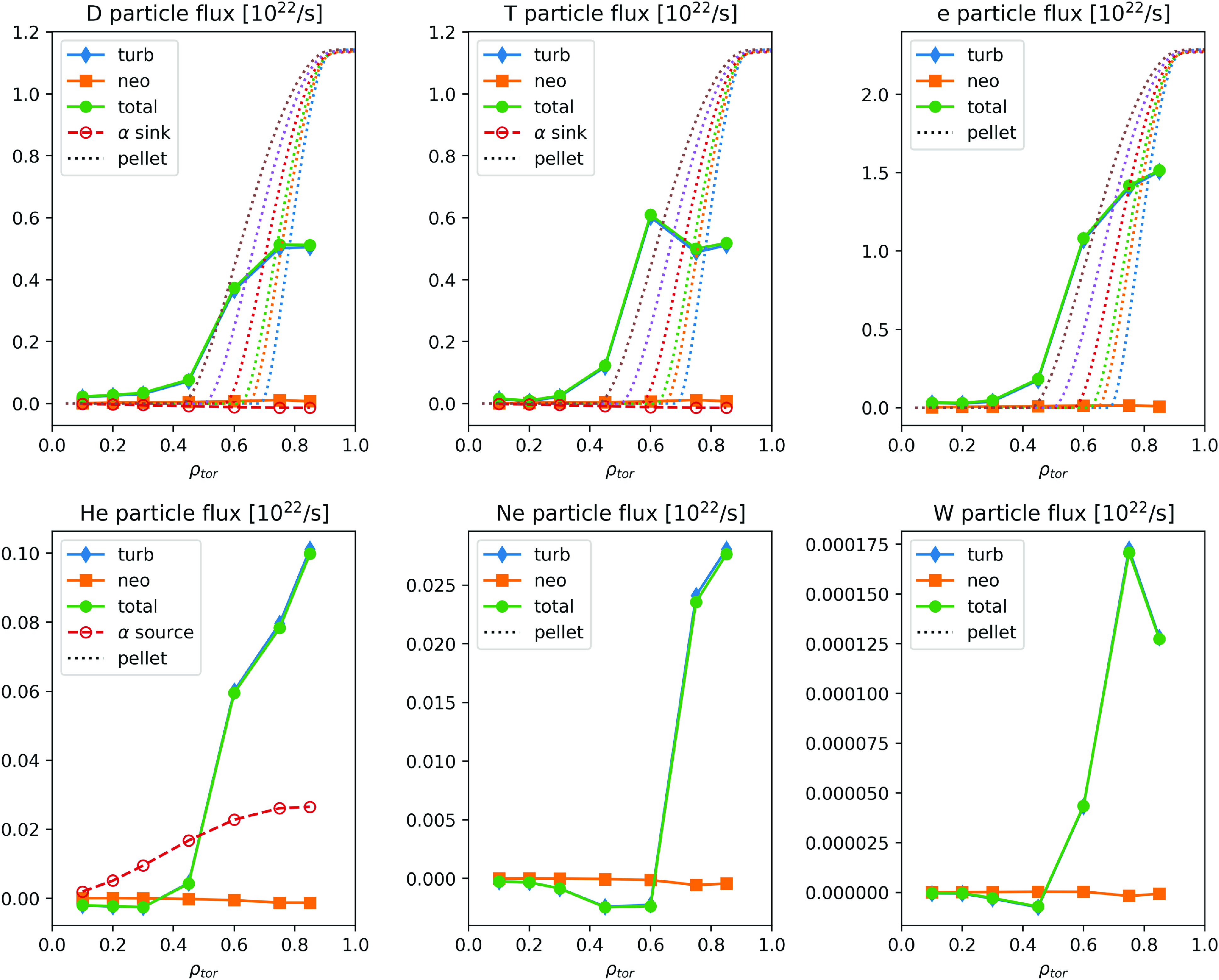
Figure 23. Particle transport fluxes are calculated for six different particle species (deuterium, tritium, electrons, helium, tungsten and neon) as a function of $\rho$
for the
$\rho$
for the $800$
MW DT fusion baseline case.
$800$
MW DT fusion baseline case.
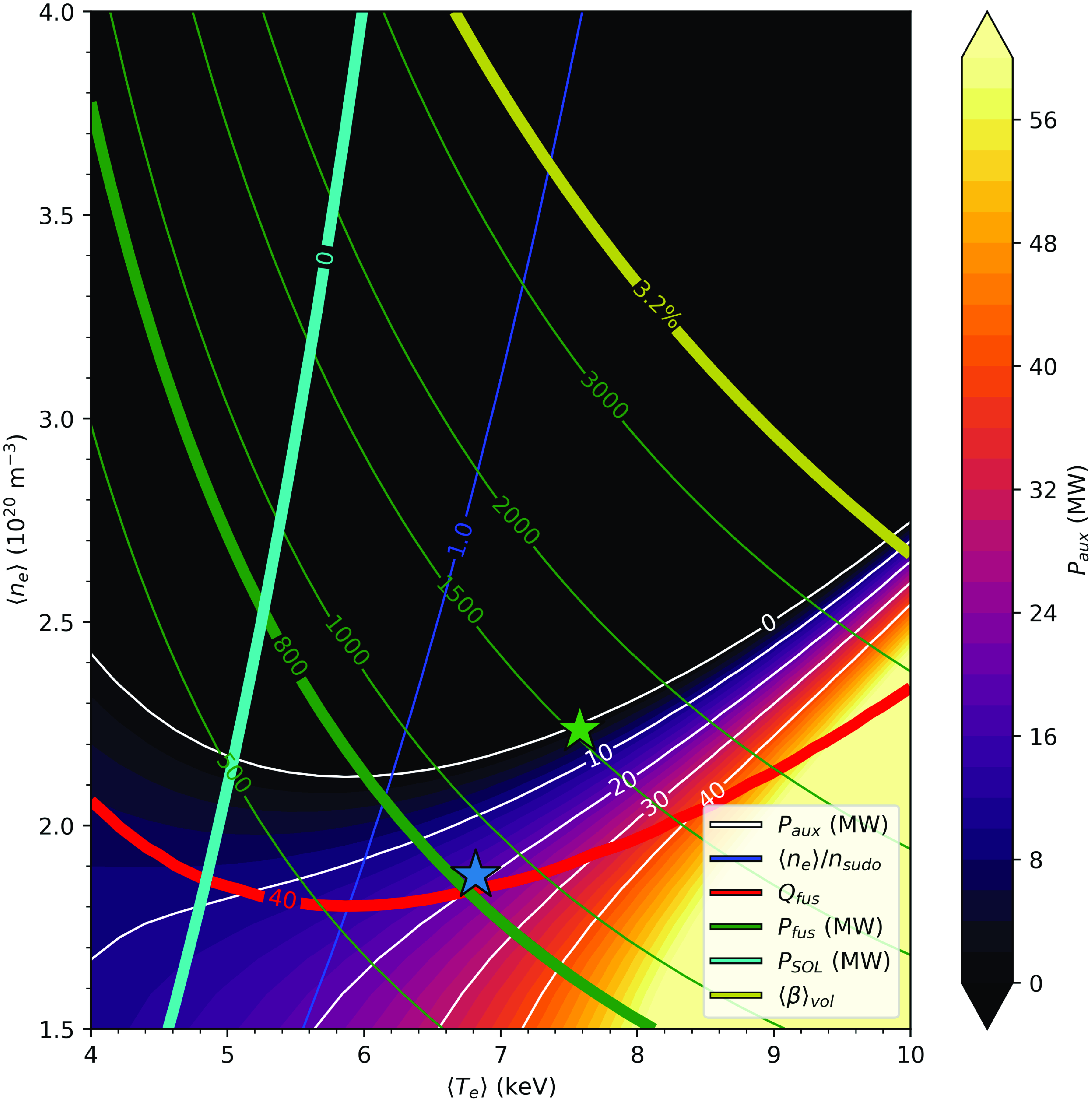
Figure 24. Operational boundaries for DT fusion are plotted as a function of the volume-averaged plasma densities and temperatures. The two stars report the results of two T3D-GX-SFINCS simulations. The blue star is the baseline case with 800 MW fusion power shown above. The green star is an ignited case with 1500 MW fusion power. White curves indicate the auxiliary power required at each point to satisfy volume-averaged power balance, assuming fixed confinement quality $f_c=1.14$
as obtained in T3D simulations. The gold curve at top right corresponds to
$f_c=1.14$
as obtained in T3D simulations. The gold curve at top right corresponds to $\langle \beta \rangle = 3.2\,\%$
. The cyan curve on the left corresponds to
$\langle \beta \rangle = 3.2\,\%$
. The cyan curve on the left corresponds to $P_{{SOL}} = P_{aux} + P_{\alpha } - P_{{rad}} = 0$
while the darker blue curve shows
$P_{{SOL}} = P_{aux} + P_{\alpha } - P_{{rad}} = 0$
while the darker blue curve shows $\langle n_e\rangle = n_{{Sudo}}$
. The solid red curve at the bottom corresponds to
$\langle n_e\rangle = n_{{Sudo}}$
. The solid red curve at the bottom corresponds to $Q = 40$
while the uppermost white curve shows
$Q = 40$
while the uppermost white curve shows $Q = \infty$
. The green contours represent lines of constant DT fusion power, with the baseline
$Q = \infty$
. The green contours represent lines of constant DT fusion power, with the baseline $P_{{fus}}=800$
MW highlighted.
$P_{{fus}}=800$
MW highlighted.
Plasma Operational Condition (POPCON) analysis of Infinity Two can be performed to evaluate the operational space for a DT FPP based on this configuration. In figure 24, performance projections are provided based on the confinement quality associated with the $800$
MW DT scenario relative to the ISS04 scaling law,
$800$
MW DT scenario relative to the ISS04 scaling law, $f_c=1.14$
. The operational space is labeled by the volume-averaged density and electron temperature. In this plot, the two stars correspond to full T3D-GX-SFINCS simulations for two different operating densities,
$f_c=1.14$
. The operational space is labeled by the volume-averaged density and electron temperature. In this plot, the two stars correspond to full T3D-GX-SFINCS simulations for two different operating densities, $\langle n_e\rangle = 1.88 \times 10^{20}$
m
$\langle n_e\rangle = 1.88 \times 10^{20}$
m $^{-3}$
and
$^{-3}$
and $2.24 \times 10^{20}$
m
$2.24 \times 10^{20}$
m $^{-3}$
. The first case (blue star) is the baseline case presented above, with 800 MW of DT fusion power and 20 MW of auxiliary power corresponding to gain
$^{-3}$
. The first case (blue star) is the baseline case presented above, with 800 MW of DT fusion power and 20 MW of auxiliary power corresponding to gain $Q=40$
. The second case (green star) is an ignited (
$Q=40$
. The second case (green star) is an ignited ( $Q=\infty$
) case producing 1500 MW fusion power. High
$Q=\infty$
) case producing 1500 MW fusion power. High $Q$
operation for Infinity Two with at least
$Q$
operation for Infinity Two with at least $800$
MW of DT fusion power is dictated by the region bounded by the four thick lines on this plot. The
$800$
MW of DT fusion power is dictated by the region bounded by the four thick lines on this plot. The $\langle \beta \rangle = 3.2\,\%$
limit from long-wavelength MHD stability boundaries is given by the thick gold curve at the upper right. The thick cyan curve on the left represents the limit
$\langle \beta \rangle = 3.2\,\%$
limit from long-wavelength MHD stability boundaries is given by the thick gold curve at the upper right. The thick cyan curve on the left represents the limit $P_{{SOL}} =P_{\alpha } - P_{{rad}} = 0$
with 100 % radiation fraction and no power reaching the scrape-off layer. The thick red curve at the bottom indicates
$P_{{SOL}} =P_{\alpha } - P_{{rad}} = 0$
with 100 % radiation fraction and no power reaching the scrape-off layer. The thick red curve at the bottom indicates $Q = 40$
scenarios, and white curves show contours of auxiliary power required at each operating point, with the uppermost white curve indicating ignition (
$Q = 40$
scenarios, and white curves show contours of auxiliary power required at each operating point, with the uppermost white curve indicating ignition ( $Q=\infty$
). Green curves represent lines of constant DT fusion power, with the baseline
$Q=\infty$
). Green curves represent lines of constant DT fusion power, with the baseline $P_{{fus}}=800$
MW highlighted with the thick green line. The Sudo limit (
$P_{{fus}}=800$
MW highlighted with the thick green line. The Sudo limit ( $\langle n_e \rangle = n_{{Sudo}}$
) is defined by the dark blue curve to the right of the thick cyan curve. From this POPCON plot, we find ignited plasmas can be attained for volume-averaged density larger than
$\langle n_e \rangle = n_{{Sudo}}$
) is defined by the dark blue curve to the right of the thick cyan curve. From this POPCON plot, we find ignited plasmas can be attained for volume-averaged density larger than $\langle n_e \rangle \approx 2.2 \times 10^{20}$
m
$\langle n_e \rangle \approx 2.2 \times 10^{20}$
m $^{-3}$
. Solutions up to
$^{-3}$
. Solutions up to $P_{{fus}} = 3000$
MW DT fusion power exist and as low as
$P_{{fus}} = 3000$
MW DT fusion power exist and as low as $\sim 800$
MW with substantial radiated power fraction, depending on the ability to operate above the Sudo density limit while maintaining good confinement.
$\sim 800$
MW with substantial radiated power fraction, depending on the ability to operate above the Sudo density limit while maintaining good confinement.
6. Divertor, blanket and shielding
In the prior sections, understanding in the areas of MHD equilibrium and stability, energetic ion confinement and neoclassical and turbulent transport is used to describe the core plasma physics of a burning stellarator. However, in order to make a compelling case that the proposed reactor will succeed, compatibility of the confinement scheme with the plasma exhaust, shielding and blanket designs must be demonstrated. In the following, we provide a brief description of the island divertor scheme available to the configuration. A novel aspect of the blanket and shielding design in a stellarator is the added flexibility provided by the three-dimensionality of the device to have non-uniform shielding and blanket thicknesses as a functions of space. We use this flexibility to show that there is sufficient space between the coil set and the plasma confinement and divertor regions to accommodate shielding and blanket solutions with tritium breeding ratio greater than unity.
The divertor design for the configuration presented here relies on the presence of an edge localized $N = 4, M = 5$
magnetic island to allow the presence of a classical island divertor. The island divertor is a primary feature of the W7-X design (Wolf et al. Reference Wolf2019). The island divertor on W7-X has proven to be very successful in its first campaign demonstrating being able to handle heat exhaust with up to
$N = 4, M = 5$
magnetic island to allow the presence of a classical island divertor. The island divertor is a primary feature of the W7-X design (Wolf et al. Reference Wolf2019). The island divertor on W7-X has proven to be very successful in its first campaign demonstrating being able to handle heat exhaust with up to $8$
MW heating power (Pedersen et al. Reference Pedersen2019). Moreover, it has been shown that divertor detachment is robustly attained in a variety of techniques involving controlling of the input power, density or impurity density (Schmitz et al. Reference Schmitz2021; Jakubowski et al. Reference Jakubowski2021). Detached operation allows for the reduction of heat flux to the divertor by more than an order of magnitude for very long pulse plasmas. The encouraging results from W7-X indicate that control of the radiating mantle’s physical location is attainable and can be a suitable solution for a stellarator reactor. The performance of the island divertor in extended pulse operation will be a focus of the next campaign of W7-X’s operation.
$8$
MW heating power (Pedersen et al. Reference Pedersen2019). Moreover, it has been shown that divertor detachment is robustly attained in a variety of techniques involving controlling of the input power, density or impurity density (Schmitz et al. Reference Schmitz2021; Jakubowski et al. Reference Jakubowski2021). Detached operation allows for the reduction of heat flux to the divertor by more than an order of magnitude for very long pulse plasmas. The encouraging results from W7-X indicate that control of the radiating mantle’s physical location is attainable and can be a suitable solution for a stellarator reactor. The performance of the island divertor in extended pulse operation will be a focus of the next campaign of W7-X’s operation.
Bolstered by the success of the W7-X program, an island divertor design is employed for the design of the present study. Theoretical modeling of the edge/divertor physics of a stellarator is not as well developed as for the core plasma confinement. A number of important physics effects need to be accounted for when modeling the divertor region. These include the competition between parallel (along field line) transport processes and cross-field transport, atomic and radiation physics, the interaction between plasmas and neutrals and impurity plasma species (Feng et al. Reference Feng, Sardei, Grigull, McCormick, Kisslinger and Reiter2006). A crucial parameter for characterizing the plasma edge is $\lambda _{q,t}$
, which is a measure of the spread of the heat flux on the divertor target. While there is considerable uncertainty about the physics that controls heat flux spreading in stellarator, there is an expectation that the relative large connection lengths
$\lambda _{q,t}$
, which is a measure of the spread of the heat flux on the divertor target. While there is considerable uncertainty about the physics that controls heat flux spreading in stellarator, there is an expectation that the relative large connection lengths $L_c$
of island divertor solutions broadens
$L_c$
of island divertor solutions broadens $\lambda _{q,t}$
beyond the narrow widths anticipated for high-field tokamaks. Moreover, there is no broadly accepted scaling of
$\lambda _{q,t}$
beyond the narrow widths anticipated for high-field tokamaks. Moreover, there is no broadly accepted scaling of $\lambda _{q,t}$
with field strength. As such, it is difficult to make predictions for
$\lambda _{q,t}$
with field strength. As such, it is difficult to make predictions for $\lambda _{q,t}$
with certainty in the divertor design.
$\lambda _{q,t}$
with certainty in the divertor design.
The heat flux on the divertor plate of a classical island divertor is calculated with diffusive modeling assuming $\lambda _{q,t} \approx 3$
cm, as shown in figure 25. The results assume
$\lambda _{q,t} \approx 3$
cm, as shown in figure 25. The results assume $8$
MW of power is conducted to the divertor plate and thus 95 % of the power is radiated. To be clear, the radiation fraction assumed here is larger than the radiation fraction from the core plasma estimate of § 5.3. The higher radiation fraction assumes the existence of a high-Z impurity introduced so as to create an effective radiative mantle. The predicted maximum heat flux on the divertor plate is
$8$
MW of power is conducted to the divertor plate and thus 95 % of the power is radiated. To be clear, the radiation fraction assumed here is larger than the radiation fraction from the core plasma estimate of § 5.3. The higher radiation fraction assumes the existence of a high-Z impurity introduced so as to create an effective radiative mantle. The predicted maximum heat flux on the divertor plate is $2.5$
MW/m
$2.5$
MW/m $^2$
. This estimate is below the nominal engineering (
$^2$
. This estimate is below the nominal engineering ( $\sim 10$
MW/m
$\sim 10$
MW/m $^2$
) limits with enough margin in case
$^2$
) limits with enough margin in case $\lambda _q$
is significantly different than the value used here. The classical island divertor is also robust to changes in plasma
$\lambda _q$
is significantly different than the value used here. The classical island divertor is also robust to changes in plasma $\langle \beta \rangle$
. Heat flux calculations using vacuum magnetic fields show qualitatively the same features as figure 25 with similar peak heat flux values.
$\langle \beta \rangle$
. Heat flux calculations using vacuum magnetic fields show qualitatively the same features as figure 25 with similar peak heat flux values.
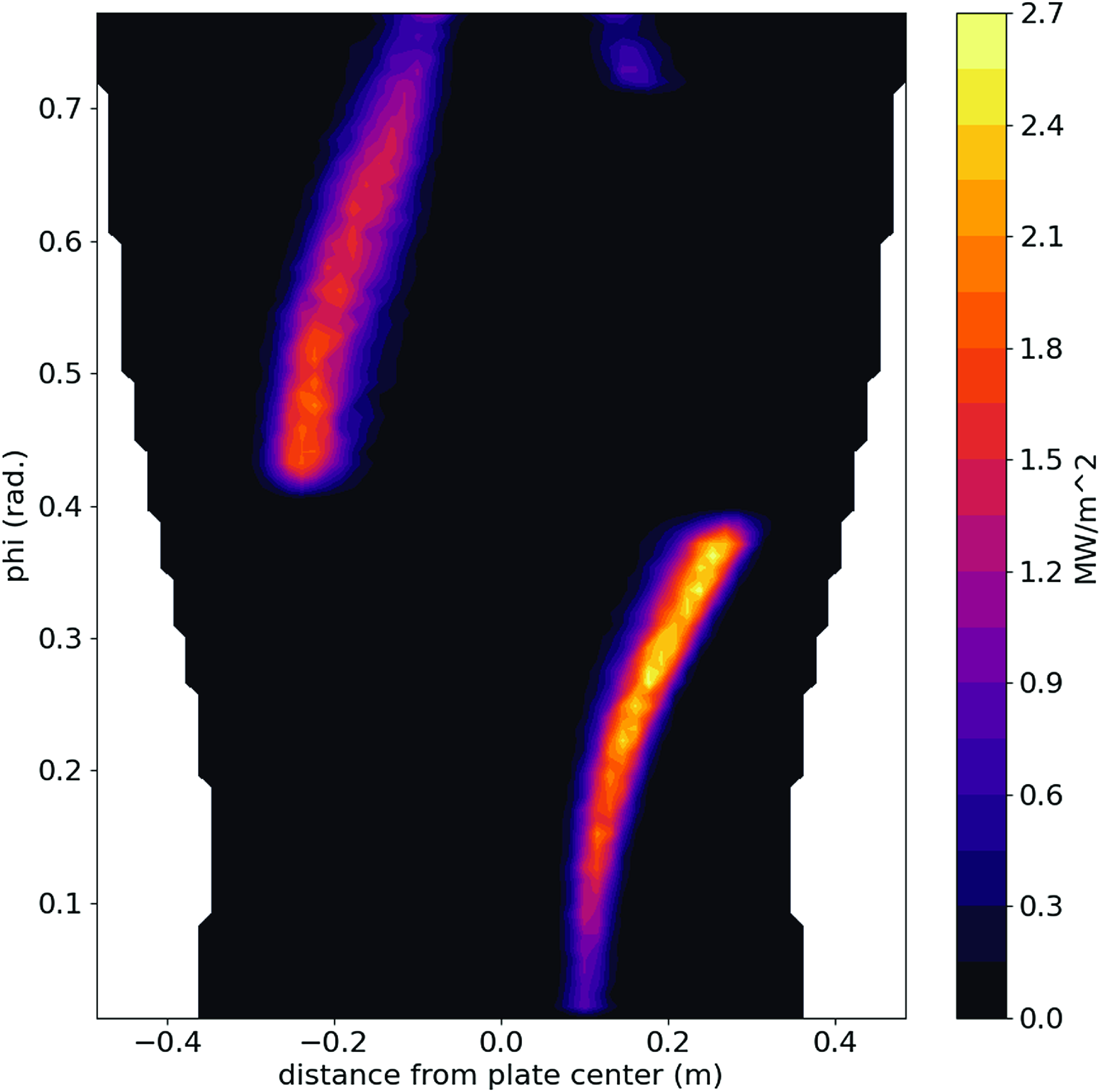
Figure 25. Contours of heat flux calculated for a classical island divertor as a function of the distance from the center of the divertor plate and toroidal angle. Here, $\lambda _{q,t} = 3$
cm.
$\lambda _{q,t} = 3$
cm.
An important role for the divertor is to deal with helium ash removal and the control of impurities (Wenzel et al. Reference Wenzel2022). While the simple island divertor described above can handle the heat flux needs of a stellarator power plant, the containment of neutrals in the W7-X divertor is inadequate for a reactor. This is very likely due to the openness of the divertor in W7-X, in part a consequence of its flexible design to accommodate multiple edge resonances. We are pondering a new divertor design, the large island backside divertor (LIBD) which is designed to address the particle control problem. The LIBD concept works on the premise that the bulk of the heat exiting the plasma moves along the island separatrix. Therefore the center of island, which receives minimal heat flux, can be the location of a mechanical structure which, if carefully designed, can be used to prevent the re-entry of neutral particles into the plasma. A diagram of the LIBD is shown in figure 26. Here it is possible to see the island dome (yellow) which is inserted into the island. The plasma particles travel along the island separatrix striking an impact surface on the backside of the dome (blue). The neutralized particles including both hydrogenic species and helium neutrals are then prevented by the dome and the baffling (not shown) from directly reentering the plasma. The result is an enhancement of particle pumping.
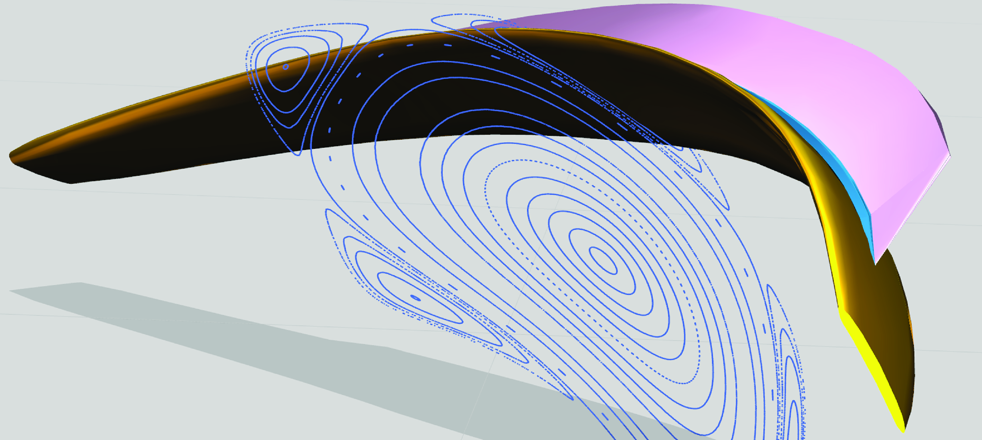
Figure 26. A 3-D cut out view of the large island backside divertor structure. A Poincaré plot at toroidal angle 22.5 $^\circ$
is overlayed. The LIBD divertor components are colored with the dome in yellow, the support in pink and the impact surfaces in blue. The baffles are not shown.
$^\circ$
is overlayed. The LIBD divertor components are colored with the dome in yellow, the support in pink and the impact surfaces in blue. The baffles are not shown.
A challenge for the LIBD divertor concept is the presence of dome structure inside the island. This feature dictates the need for an island of sufficently large radial extent (in a 3-D stellarator divertor, the ‘radial’ extent of the island divertor varies greatly as a function of poloidal and toroidal angle), as the dome needs to retain structural integrity and be actively cooled. Large islands are most easily created in low-shear stellarators, like Infinity Two. However, large islands imply long connection lengths. Hence, perpendicular diffusion processes can be very effective in widening the SOL.
A circumstance that is challenging to the LIBD occurs when perpendicular transport is sufficiently large that the island width is comparable to the SOL width. In this event, cross-field transport can cause particles and heat to transport across fields towards the dome before parallel transport can move them around the island to the backside of the dome. For the present Infinity Two divertor design, the bulk of expelled heat flux hits the desired impact surface (instead of the dome) when $\lambda _{q,t} \lt 1.5$
cm (Bader et al. Reference Bader2025), a value somewhat smaller than is seen in W7-X (Killer et al. Reference Killer2019; Niemann et al. Reference Niemann2020). In principle, a small
$\lambda _{q,t} \lt 1.5$
cm (Bader et al. Reference Bader2025), a value somewhat smaller than is seen in W7-X (Killer et al. Reference Killer2019; Niemann et al. Reference Niemann2020). In principle, a small $\lambda _{q,t}$
can be realized if there is beneficial
$\lambda _{q,t}$
can be realized if there is beneficial $B$
scaling to the cross-field transport processes. Another approach would be to increase the island size by increasing the radial resonant magnetic field amplitude through a set of auxiliary coils.
$B$
scaling to the cross-field transport processes. Another approach would be to increase the island size by increasing the radial resonant magnetic field amplitude through a set of auxiliary coils.
In addition to challenges in plasma physics, the breeding blanket and tritium fuel cycle (TFC) related aspects of DT fusion systems embody fundamental feasibility and attractiveness issues in the development of commercial fusion energy. This includes designing for a closed TFC, overall system efficiency and sizing through nuclear shielding efficacy (Abdou et al. Reference Abdou, Morley, Smolentzev, Ying, Malang, Rowcliffe and Ulrickson2015). For these reasons, the selection, design, and optimization of a suitable blanket configuration for an advanced high-field stellarator concept is seen as a key feasibility issue and has been incorporated as a vital necessary part of the FPP physics basis from the onset. In this regard, efforts focused on the timely identification, analysis, evaluation and down-selection of potential blanket concepts. The focus of this portion of the physics basis program was to identify a baseline blanket which can be rapidly deployed for Infinity Two while also maintaining flexibility and opportunities for higher performing concepts later in development. It also included the development of novel, physics-based tools and analytical capabilities required to perform scoping study of the blanket design concepts proposed in the literature. The neutron wall loading show in figure 27(a) is one such parameter which was evaluated using these tools, and is a fundamental constraint that varies with surface coordinates on the first wall. Similarly, the allowable radial build distance from the plasma surface to the magnet was also evaluated, as shown in figure 27(b), and has strong implications on overall breeder performance. Parameters such as these were used to compare various blanket concepts and analyze their suitability for highly non-uniform stellarator configurations. They will also be employed for rapid screening and evaluation of engineering performance as part of the overall stellarator optimization program moving forward.
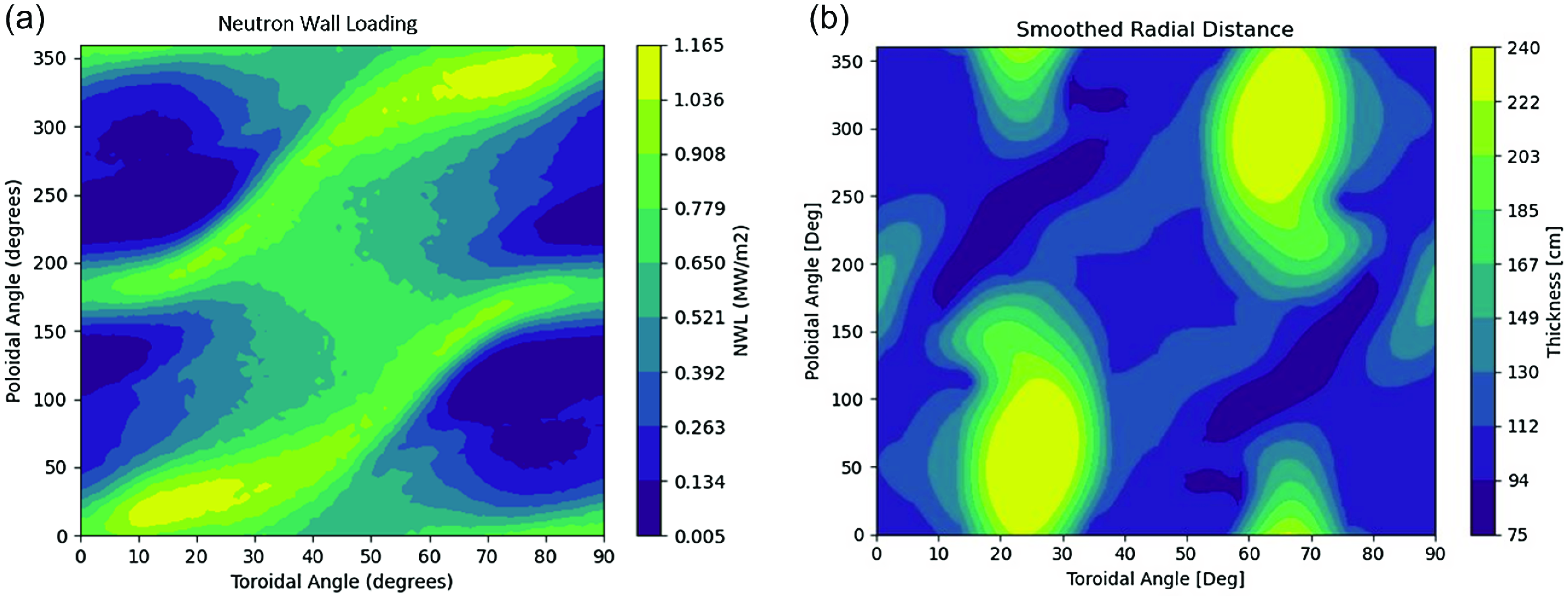
Figure 27. (a) Neutron wall loading for Infinity Two plasma configuration as a DT neutron source. (b) Available radial build thickness for Infinity Two plasma configuration constrained by coils.
The results of the blanket analysis indicate that gas-cooled solid breeder designs such as the helium-cooled pebble bed (HCBP) (Zhou et al. Reference Zhou, Hernandez, Pereslavtsev, Kiss, Retheesh, Maqueda and Park2023) are the most promising concepts. This is primarily motivated by the neutronics performance at appliable blanket build depths as well as the relatively mature technology basis. In addition, there appears to be significant opportunities for continued improvement in this family of concepts using new materials, coolant, multipliers and designs/design methodology to better meet the needs of stellarators. The PbLi family of concepts, particularly the dual-cooled lithium lead (DCLL) (Smolentsev et al. Reference Smolentsev, Morley, Abdou and Malang2015), offers a compelling alternative to solid blanket concepts. They have synergistic developmental pathways while simultaneously mitigating much of the technical risk of solid breeder designs and will be carried forward as a risk mitigation approach.
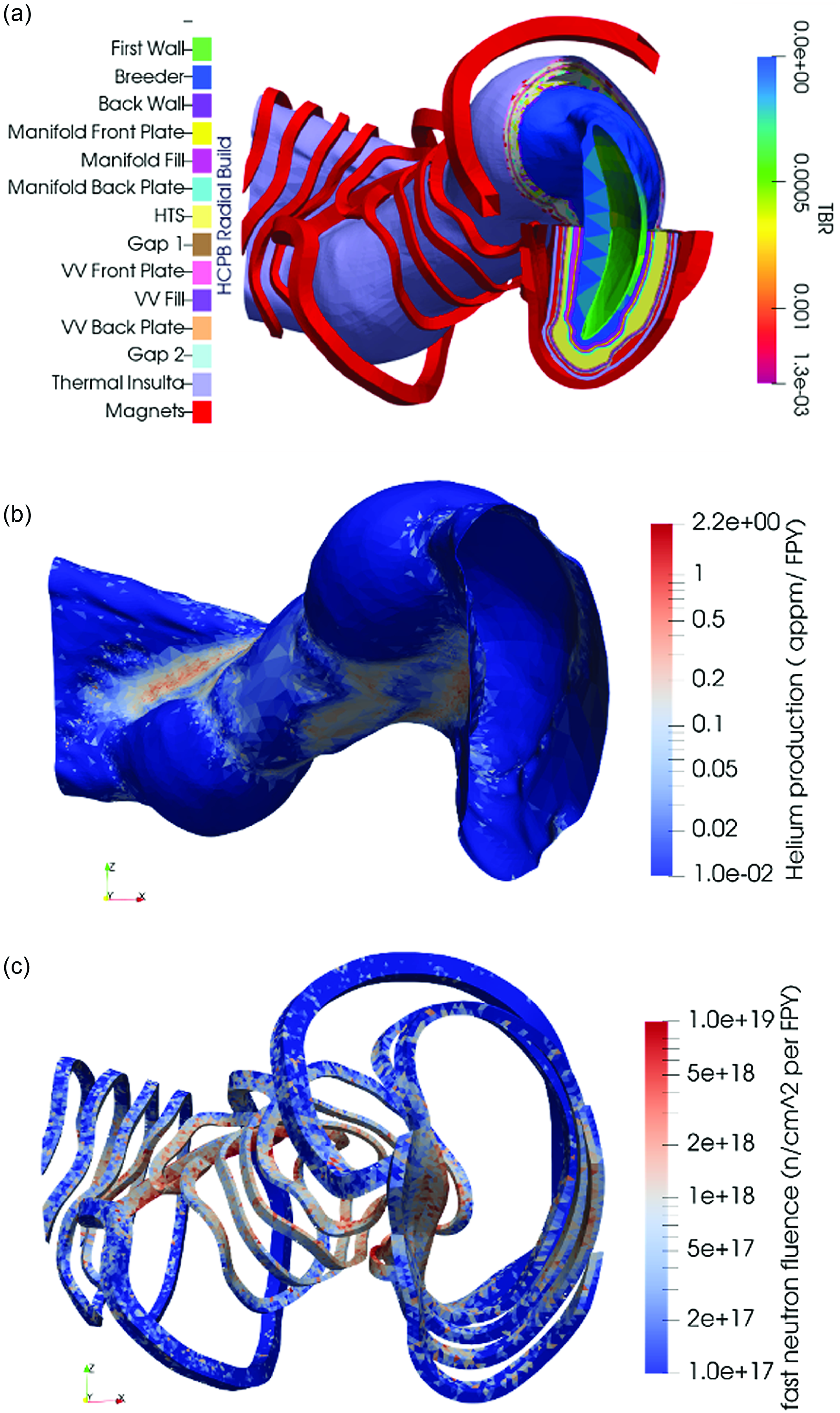
Figure 28. (a) Stellarator geometry with mesh showing the spatial distribution of tritium breeding in the breeder zone. (b) Vacuum vessel only mesh showing the spatial distribution of He production by neutron-induced transmutation. (c) Magnet coil only mesh showing the spatial distribution of fast neutron fluence.
From a neutronics perspective, both the HCBP and DCLL were evaluated against the Infinity Two configuration. Figure 28 shows a homogenized 3-D neutronics model and associated component layers which were constructed using a ParaStell-based tool suite (Moreno et al. Reference Moreno, Bader and Wilson2024) for the Infinity Two configuration and an HCPB blanket. The objective of this tool suite is focused on the automated buildout of stellarator in-vessel components using non-uniform builds for both optimized tritium breeding and shielding. Figure 28(a) also shows the spatial distribution of the tritium breeding calculation, which when integrated indicates that the HCPB blanket concept can achieve a tritium breeding ratio (TBR) of 1.30. It should be noted that this value is for an idealized system only and provides what is seen as an acceptable margin in performance given the low engineering fidelity models used in this study. In addition, the neutronics simulations show viability of the current approach for the optimization of shielding for lifetime components in complex 3-D geometries. Key metrics included an average He production in the vacuum vessel (figure 28
b) of $0.03$
atomic ppm per full-power year, which is well below the target limit of
$0.03$
atomic ppm per full-power year, which is well below the target limit of $0.2$
atomic ppm per full-power year, and near-appropriate shielding of the magnets (figure 28
c) with an average fast fluence of
$0.2$
atomic ppm per full-power year, and near-appropriate shielding of the magnets (figure 28
c) with an average fast fluence of $1.3 \times 10^{18}\,\rm n^-{^1}cm^-{^2}$
per full-power year, which is comparable to the target limit of
$1.3 \times 10^{18}\,\rm n^-{^1}cm^-{^2}$
per full-power year, which is comparable to the target limit of $1.0\times 10^{18}\,\rm n^-{^1}cm^-{^2}$
per full-power year. The absolute lifetime limits (
$1.0\times 10^{18}\,\rm n^-{^1}cm^-{^2}$
per full-power year. The absolute lifetime limits ( $5 \times 10^{18}\,\rm n^-{^1}cm^-{^2}$
) used are derived from prior studies (El-Guebaly Reference El-Guebaly2018) and applied to an Infinity Two target lifetime of five full-power years. Further optimization is required to further reduce the fast fluence in the magnets and mitigate localized peak damage metrics, but no fundamental hurdles are currently envisioned towards their resolution using the optimization scheme developed as a part of this study.
$5 \times 10^{18}\,\rm n^-{^1}cm^-{^2}$
) used are derived from prior studies (El-Guebaly Reference El-Guebaly2018) and applied to an Infinity Two target lifetime of five full-power years. Further optimization is required to further reduce the fast fluence in the magnets and mitigate localized peak damage metrics, but no fundamental hurdles are currently envisioned towards their resolution using the optimization scheme developed as a part of this study.
In addition, the HCPB was evaluated for the Infinity Two configuration with regards to both thermal performance and TFC considerations. The thermal analysis indicates that a reasonably high thermal efficiency ( $\gt 30\,\%$
) with acceptable margin is readily achievable when the HCPB is paired with a simple Rankine cycle using reheat. In addition, the TFC analysis shows compatibility with a closed fuel cycle. This includes anticipated operational inventories of less than a kg (
$\gt 30\,\%$
) with acceptable margin is readily achievable when the HCPB is paired with a simple Rankine cycle using reheat. In addition, the TFC analysis shows compatibility with a closed fuel cycle. This includes anticipated operational inventories of less than a kg ( $\sim 675\,\rm g$
) for the Infinity Two configuration given the relevant technology and physics regimes, as well as a required TBR of less than
$\sim 675\,\rm g$
) for the Infinity Two configuration given the relevant technology and physics regimes, as well as a required TBR of less than $1.05$
(
$1.05$
( $\sim 1.023$
) for a driver blanket with no inventory doubling. Although further optimization and engineering design is still required, at the physics basis stage, all initial targets have been met for the Infinity Two configuration from a blanket and fuel cycle perspective.
$\sim 1.023$
) for a driver blanket with no inventory doubling. Although further optimization and engineering design is still required, at the physics basis stage, all initial targets have been met for the Infinity Two configuration from a blanket and fuel cycle perspective.
7. Summary and discussion
In this set of papers, the physics basis for the realization of fusion power using the stellarator concept is presented. The configuration examined in this study, Infinity Two, is a four-field period, $A = 10, R = 12. 5$
m QI stellarator optimized for improved confinement using a max-
$A = 10, R = 12. 5$
m QI stellarator optimized for improved confinement using a max- $J$
principle and high magnetic field (
$J$
principle and high magnetic field ( $\langle B\rangle = 9$
T). An
$\langle B\rangle = 9$
T). An $800$
MW DT fusion high fusion gain (
$800$
MW DT fusion high fusion gain ( $Q \gt 40$
) scenario is envisioned as the base operating point. At this operating point, the configuration has robust equilibrium magnetic surfaces and is stable to both local and global MHD instabilities. The MHD stability analysis shows Infinity Two is stable up to
$Q \gt 40$
) scenario is envisioned as the base operating point. At this operating point, the configuration has robust equilibrium magnetic surfaces and is stable to both local and global MHD instabilities. The MHD stability analysis shows Infinity Two is stable up to $\langle \beta \rangle = 3.2\,\%$
, roughly twice the value of the base operating point. The configuration has excellent neoclassical transport properties and small equilibrium bootstrap current (
$\langle \beta \rangle = 3.2\,\%$
, roughly twice the value of the base operating point. The configuration has excellent neoclassical transport properties and small equilibrium bootstrap current ( $|I_{bootstrap}| \sim 2 kA$
). The energetic ion confinement for this configuration is excellent. Collisionless GC calculations with initial alpha-particle distributions consistent with the Infinity Two’s reactivity profile show small
$|I_{bootstrap}| \sim 2 kA$
). The energetic ion confinement for this configuration is excellent. Collisionless GC calculations with initial alpha-particle distributions consistent with the Infinity Two’s reactivity profile show small $(\sim 0.5\,\%)$
losses to the last closed flux surface due to poor orbits. Calculations using full orbits with Coulomb collisions show that at most
$(\sim 0.5\,\%)$
losses to the last closed flux surface due to poor orbits. Calculations using full orbits with Coulomb collisions show that at most $1.5\,\%$
of alpha energy losses to the first wall with peak alpha-particle-induced heat loads less than
$1.5\,\%$
of alpha energy losses to the first wall with peak alpha-particle-induced heat loads less than $2.5$
MW m
$2.5$
MW m ${}^{-2}$
. Moreover, AE activity is muted with the most dangerous modes stabilized by high density operation. We have yet to perform a detailed coil sensitivity study to determine the robustness of the good energetic particle confinement to field perturbations. However, from an MHD equilibrium and stability standpoint, small field error effects should not produce dramatic changes as the rotational transform profile avoids major resonances and the operational
${}^{-2}$
. Moreover, AE activity is muted with the most dangerous modes stabilized by high density operation. We have yet to perform a detailed coil sensitivity study to determine the robustness of the good energetic particle confinement to field perturbations. However, from an MHD equilibrium and stability standpoint, small field error effects should not produce dramatic changes as the rotational transform profile avoids major resonances and the operational $\langle \beta \rangle$
is far from stability limits.
$\langle \beta \rangle$
is far from stability limits.
A reduced turbulent transport scenario is developed that is consistent with the use of continuous pellet fueling. In our studies, a density is profile is assumed that is largely flat in the core of the stellarator but shows a prominent density gradient in the confinement region ( $0.6 \lt \rho \lt 0.9$
) consistent with a simple pellet ablation model. In the confinement region, the density gradient works to alleviate the impact of ITG turbulence and is assisted by appealing to reduced stiffness through 3-D shaping. The impact of the density gradient on micro-instabilities driven by non-adiabatic electron responses are eased by the presence of the max-
$0.6 \lt \rho \lt 0.9$
) consistent with a simple pellet ablation model. In the confinement region, the density gradient works to alleviate the impact of ITG turbulence and is assisted by appealing to reduced stiffness through 3-D shaping. The impact of the density gradient on micro-instabilities driven by non-adiabatic electron responses are eased by the presence of the max- $J$
condition and the use of high field to avoid operating near KBM stability boundaries.
$J$
condition and the use of high field to avoid operating near KBM stability boundaries.
Self-consistent predictions of the plasma profiles in DT fusion plasmas are simulated using the T3D-GX-SFINCS transport framework. These calculations account for turbulent transport processes as predicted from nonlinear gyrokinetic simulations, neoclassical transport from drift kinetic solutions, alpha and auxiliary heating, collisional energy exchange and radiation processes. At sufficiently high densities, $\langle n_e\rangle \gt 2.2 \times 10^{20}$
m
$\langle n_e\rangle \gt 2.2 \times 10^{20}$
m $^{-3}$
, ignited plasmas are predicted. One simulation is presented showing
$^{-3}$
, ignited plasmas are predicted. One simulation is presented showing $800$
MW DT fusion with
$800$
MW DT fusion with $20$
MW of auxiliary power at
$20$
MW of auxiliary power at $\langle n_e\rangle = 1.9 \times 10^{20}$
m
$\langle n_e\rangle = 1.9 \times 10^{20}$
m $^{-3}$
. At this higher density, bremsstrahlung losses are substantial with
$^{-3}$
. At this higher density, bremsstrahlung losses are substantial with $P_{rad}/P_{fusion} = 0.41$
. However, the Sudo limit is not violated
$P_{rad}/P_{fusion} = 0.41$
. However, the Sudo limit is not violated $\langle n_e\rangle /n_{Sudo} = 0.92$
. Moreover, the configuration stays ideal MHD stable and maintains good energetic ion confinement properties. Neoclassical transport is subdominant to turbulent transport at all radii and impurity transport is outward at outer radii. POPCON analysis predicts Infinity Two can achieve high
$\langle n_e\rangle /n_{Sudo} = 0.92$
. Moreover, the configuration stays ideal MHD stable and maintains good energetic ion confinement properties. Neoclassical transport is subdominant to turbulent transport at all radii and impurity transport is outward at outer radii. POPCON analysis predicts Infinity Two can achieve high $Q \gt 40$
operations over a broad parameter space while maintaining robust MHD equilibrium and stability and avoiding radiative collapse.
$Q \gt 40$
operations over a broad parameter space while maintaining robust MHD equilibrium and stability and avoiding radiative collapse.
The Infinity Two configuration accommodates an island divertor associated with the edge ${{\iota\kern-1pt\!\mbox{-}\kern0.5pt}}(a) = 4/5$
resonant surface. Consequently, the design can build on the encouraging results from W7-X which demonstrate robust radiative divertor operation to handle energy exhaust. To improve the particle handling capabilities of the island divertor, a proposed modification, the large island backside divertor concept, is introduced. The configuration’s coil set enables sufficient room for both neutron shielding and a blanket solution. Initial calculations indicate tritium breeding ratios well above unity for a HCBP breeder concept.
${{\iota\kern-1pt\!\mbox{-}\kern0.5pt}}(a) = 4/5$
resonant surface. Consequently, the design can build on the encouraging results from W7-X which demonstrate robust radiative divertor operation to handle energy exhaust. To improve the particle handling capabilities of the island divertor, a proposed modification, the large island backside divertor concept, is introduced. The configuration’s coil set enables sufficient room for both neutron shielding and a blanket solution. Initial calculations indicate tritium breeding ratios well above unity for a HCBP breeder concept.
While the configuration is assessed for an $800$
MW DT fusion operating power, the plasma physics studies indicate that a far larger fusion power is possible. However, enhanced fusion power provides a greater challenge for the divertor and first wall. This study did not provide a comprehensive optimized solution for the integrated fusion science and engineering system, but this will be certainly an emphasis of Type One Energy moving forward.
$800$
MW DT fusion operating power, the plasma physics studies indicate that a far larger fusion power is possible. However, enhanced fusion power provides a greater challenge for the divertor and first wall. This study did not provide a comprehensive optimized solution for the integrated fusion science and engineering system, but this will be certainly an emphasis of Type One Energy moving forward.
One area that the physics studies did not completely resolve is in the area of core-edge coupling. The core plasma physics studies largely rely on free-boundary MHD equilibrium solutions that do not accurately describe the edge-island divertor region. As such, boundary conditions used in transport and MHD evaluations may not be consistent with solutions in the edge region. However, our ability to accurately model the foundational plasma physics in the island divertor region is not at the level of core plasma physics. Moreover, the presence of the island distorts the magnetic surface shapes in the topologically toroidal flux surface region outside of the separatrix. Therefore there is some uncertainty in our modeling of the plasma physics in the edge ( $\rho \sim 0.9 - 1.0$
).
$\rho \sim 0.9 - 1.0$
).
This uncertainty, in part, motivates the design, construction and operation of a new stellarator facility in order to test our ability to predict stellarator performance as well as fill in the gaps for areas where there is uncertainty. To this end, Type One Energy is planning to construct a stellarator facility (named Infinity One) with nominal parameters $R \sim 3$
m,
$R \sim 3$
m, $B \sim 3$
T. The primary physics mission of Infinity One includes tests to demonstrate our ability to improve turbulent transport in a stellarator, and the compatibility of this optimized stellarator with an island divertor concept that provides scalable solutions for power and particle handling.
$B \sim 3$
T. The primary physics mission of Infinity One includes tests to demonstrate our ability to improve turbulent transport in a stellarator, and the compatibility of this optimized stellarator with an island divertor concept that provides scalable solutions for power and particle handling.
Acknowledgements
We also gratefully acknowledge the use of computational resources managed and supported by Princeton Research Computing, a consortium of groups including the Princeton Institute for Computational Science and Engineering (PICSciE) and the Office of Information Technology’s High Performance Computing Center and Visualization Laboratory at Princeton University.
Editor Per Helander thanks the referees for their advice in evaluating this article.
Funding
This work was supported by Type One Energy. We gratefully acknowledge our use of computing resources and facilities funded by the U.S. Department of Energy, including: the Oak Ridge Leadership Computing Facility at the Oak Ridge National Laboratory, which is supported by the Office of Science of the U.S. Department of Energy under Contract No. DE-AC 05-00OR22725, using awards for computing time on Summit and Frontier; the National Energy Research Scientific Computing Center (NERSC), a Department of Energy Office of Science User Facility, using NERSC awards FES-ERCAP27470 and FES-ERCAP0031820 for computing time on Perlmutter; the Argonne Leadership Computing Facility, a U.S. DOE Office of Science user facility at Argonne National Laboratory, which is supported by the Office of Science of the U.S. DOE under Contract No. DE-AC 02–06CH11357, using an award for computing time on Polaris provided by the U.S. Department of Energy’s (DOE) Innovative and Novel Computational Impact on Theory and Experiment (INCITE) Program.
Declaration of interests
The work of M.L. and W.D. was performed as consultants and was not part of the employees’ responsibilities to the University of Maryland. The work of C.H. and M.S.T. was performed as a consultant and was not part of the employees’ responsibilities at the University of California-San Diego. The work of J.V.R. was performed as a consultant and was not part of the employee’s responsibilities at the University of Texas.
Appendix A. Assessment formulae
Here, we provide analytic formulae employed for various metrics employed to evaluate stellarator configurations generated during the course of this study. The equilibrium magnetic field is written
 \begin{equation} \textbf{B} = \nabla \Psi \times \nabla \theta + \nabla \zeta \times \nabla \Phi, \end{equation}
where the toroidal and poloidal flux functions are magnetic surface functions $\Psi = \Psi (s)$
,
$\Psi = \Psi (s)$
, $\Phi = \Phi (s)$
,
$\Phi = \Phi (s)$
, $s = \Psi /\Psi _a$
,
$s = \Psi /\Psi _a$
, $\theta$
and
$\theta$
and $\zeta$
are straight field line poloidal and toroidal angles, respectively and
$\zeta$
are straight field line poloidal and toroidal angles, respectively and $d\Phi /d\Psi = {{\iota\kern-1pt\!\mbox{-}\kern0.5pt}}$
is the rotational transform profile. A flux surface averaging operator is defined by
$d\Phi /d\Psi = {{\iota\kern-1pt\!\mbox{-}\kern0.5pt}}$
is the rotational transform profile. A flux surface averaging operator is defined by
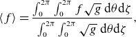 \begin{equation} \langle f \rangle = \frac {\int _0^{2\pi } \int _0^{2\pi } f \sqrt {g} \hspace {1mm}\mathrm{d}\theta \mathrm{d}\zeta }{ \int _0^{2\pi } \int _0^{2\pi } \sqrt {g}\hspace {1mm}\mathrm{d}\theta \mathrm{d}\zeta }, \end{equation}
where $\sqrt {g} = 1/\nabla s\cdot \nabla \theta \times \nabla \zeta$
and
$\sqrt {g} = 1/\nabla s\cdot \nabla \theta \times \nabla \zeta$
and $V' = dV/ds = \int _0^{2\pi } \int _0^{2\pi } \sqrt {g} \hspace {1mm} \mathrm{d}\theta \mathrm{d}\zeta$
.
$V' = dV/ds = \int _0^{2\pi } \int _0^{2\pi } \sqrt {g} \hspace {1mm} \mathrm{d}\theta \mathrm{d}\zeta$
.
The Mercier criterion for MHD stability to local interchange modes can be written (Carreras et al. Reference Carreras, Dominguez, Garcia, Lynch, Lyon, Cary, Hanson and Navarro1988)
 \begin{equation} D_M = D_s + D_W + D_V + D_G \geqslant 0, \end{equation}
where
 \begin{equation} D_s = \frac {s}{{{\iota\kern-1pt\!\mbox{-}\kern0.5pt}}^2 \pi ^2} \frac {(\Psi ''\Phi ')^2}{4}, \end{equation}
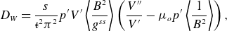 \begin{equation} D_W = \frac {s}{{{\iota\kern-1pt\!\mbox{-}\kern0.5pt}}^2 \pi ^2} p' V' \left\langle \frac {B^2}{g^{ss}}\right\rangle \left(\frac {V''}{V'} - \mu _o p' \left\langle \frac {1}{B^2}\right\rangle \right), \end{equation}
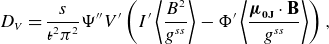 \begin{equation} D_V = \frac {s}{{{\iota\kern-1pt\!\mbox{-}\kern0.5pt}}^2\pi ^2} \Psi '' V' \left(I' \left\langle \frac {B^2}{g^{ss}}\right\rangle - \Phi ' \left\langle \frac {\boldsymbol{\mu}_\textbf{0J}\cdot \textbf{B}}{g^{ss}}\right\rangle \right), \end{equation}
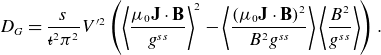 \begin{equation} D_G = \frac {s}{{{\iota\kern-1pt\!\mbox{-}\kern0.5pt}}^2\pi ^2} V'^2\left(\left\langle \frac {\mu _0 \textbf{J}\cdot \textbf{B}}{g^{ss}}\right\rangle ^2 - \left\langle \frac {(\mu _0 \textbf{J}\cdot \textbf{B})^2}{B^2 g^{ss}}\right\rangle \left\langle \frac {B^2}{g^{ss}}\right\rangle \right) .\\[6pt] \end{equation}
Here, $f' = df/ds$
,
$f' = df/ds$
, $g^{ss} = \nabla s\cdot \nabla s$
and
$g^{ss} = \nabla s\cdot \nabla s$
and $I'$
denotes the net enclosed toroidal current.
$I'$
denotes the net enclosed toroidal current.
For ideal MHD ballooning instability, it is convenient to write the equilibrium field $\textbf{B} = \nabla \Psi \times \nabla \alpha$
, where
$\textbf{B} = \nabla \Psi \times \nabla \alpha$
, where $\alpha = \theta - {{\iota\kern-1pt\!\mbox{-}\kern0.5pt}} \zeta$
. With this form, wavenumbers perpendicular to the magnetic field can be written
$\alpha = \theta - {{\iota\kern-1pt\!\mbox{-}\kern0.5pt}} \zeta$
. With this form, wavenumbers perpendicular to the magnetic field can be written $\textbf{k}_{\perp } = k_s \nabla s + k_{\alpha } \nabla \alpha$
. Marginal stability to infinite-
$\textbf{k}_{\perp } = k_s \nabla s + k_{\alpha } \nabla \alpha$
. Marginal stability to infinite- $n$
ideal MHD instabilities is governed by the ideal ballooning equation for eigenmode
$n$
ideal MHD instabilities is governed by the ideal ballooning equation for eigenmode $X$
$X$
 \begin{equation} \textbf{B}\cdot \nabla \left[\frac {k_{\perp }^2}{B^2}\textbf{B}\cdot \nabla X\right] + 2\mu _0 \frac {\textbf{B}\times \textbf{k}_{\perp }\cdot \vec {\kappa }}{B^2} \frac {\textbf{B}\times \textbf{k}_{\perp }\cdot \nabla p}{B^2} X = - \omega ^2 \rho \mu _o \frac {|k_{\perp }|^2}{B^2} X, \end{equation}
where $p$
and
$p$
and $\rho$
are the equilibrium pressure and mass density and
$\rho$
are the equilibrium pressure and mass density and $\vec {\kappa } = (\hat {\textbf{b}}\cdot \nabla )\hat {\textbf{b}}$
is the curvature vector for unit vector
$\vec {\kappa } = (\hat {\textbf{b}}\cdot \nabla )\hat {\textbf{b}}$
is the curvature vector for unit vector $\hat {\textbf{b}} = \textbf{B}/B$
.
$\hat {\textbf{b}} = \textbf{B}/B$
.
The quantity $\unicode{x1D6E4} _c$
used to assess energetic particle confinement utilizes calculations of the second adiabatic invariant (3.1), to denote
$\unicode{x1D6E4} _c$
used to assess energetic particle confinement utilizes calculations of the second adiabatic invariant (3.1), to denote $J = J(s,\alpha )$
. Here,
$J = J(s,\alpha )$
. Here, $\unicode{x1D6E4} _c$
is given by
$\unicode{x1D6E4} _c$
is given by
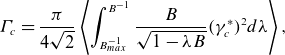 \begin{equation} \unicode{x1D6E4} _c = \frac {\pi }{4\sqrt {2}} \left\langle \int _{B_{max}^{-1}}^{B^{-1}} \frac {B}{\sqrt {1 - \lambda B}} (\gamma _c^*)^2 d\lambda \right\rangle, \end{equation}
where
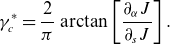 \begin{equation} \gamma _c^* = \frac {2}{\pi } \arctan \left[\frac {\partial _{\alpha } J}{\partial _s J}\right]. \end{equation}
The neoclassical transport coefficient $\epsilon _{eff}$
is computed from
$\epsilon _{eff}$
is computed from
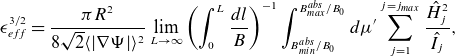 \begin{equation} \epsilon _{eff}^{3/2} = \frac {\pi R^2}{8\sqrt {2} \langle |\nabla \Psi |\rangle ^2} \lim _{L\rightarrow \infty } \left(\int _0^{L} \frac {dl}{B}\right)^{-1} \int _{B_{min}^{abs}/B_0}^{B_{max}^{abs}/B_0} d\mu ' \sum _{j = 1}^{j = j_{max}} \frac {\hat {H}_j^2}{\hat {I}_j}, \end{equation}
where
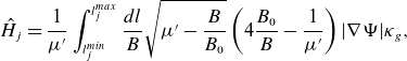 \begin{equation} \hat {H}_j = \frac {1}{\mu '} \int _{l_j^{min}}^{l_j^{max}} \frac {dl}{B} \sqrt {\mu ' - \frac {B}{B_0}} \left(4\frac {B_0}{B} - \frac {1}{\mu '}\right) |\nabla \Psi | \kappa _g, \end{equation}
 \begin{equation} \hat {I}_j = \int _{l_j^{min}}^{l_j^{max}} \frac {dl}{B} \sqrt {1 - \frac {B}{B_0 \mu '}}, \\[6pt] \end{equation}
where $\kappa _g = \hat {b}\times \vec {\kappa }\cdot \nabla \Psi /|\nabla \Psi |$
is the geodesic curvature. The calculation is carried out by integrating along a field line over a sufficiently large distance
$\kappa _g = \hat {b}\times \vec {\kappa }\cdot \nabla \Psi /|\nabla \Psi |$
is the geodesic curvature. The calculation is carried out by integrating along a field line over a sufficiently large distance $L$
and by integrating over the normalized perpendicular adiabatic invariant of the trapped particles
$L$
and by integrating over the normalized perpendicular adiabatic invariant of the trapped particles $\mu '$
. The quantities
$\mu '$
. The quantities $B_{min}^{abs}$
and
$B_{min}^{abs}$
and $B_{max}^{abs}$
denote the minimum and maximum amplitude of the magnetic field strength over the interval
$B_{max}^{abs}$
denote the minimum and maximum amplitude of the magnetic field strength over the interval $0 \lt l \lt L$
. The quantities
$0 \lt l \lt L$
. The quantities $l_{min}$
and
$l_{min}$
and $l_{max}$
within the sum over in
$l_{max}$
within the sum over in $j$
correspond to the turning points of the trapped particles in well
$j$
correspond to the turning points of the trapped particles in well $j$
.
$j$
.


 Open access