1 Introduction
High-power ultraviolet (UV) lasers are desirable for many applications, including laser conditioning, micro-nano fabrication, laser-propelled space debris removal, quantum optics, and nonlinear optical measurement[Reference Köttig, Tani, Biersach, Travers and Russell1-Reference Wang, Ma, Wang, Hu, Xu and Hao8]. Owing to limitations in the emission spectra of gain crystals, high-power UV lasers are usually obtained by third harmonic generation (THG) from near-infrared lasers. THG is a technique of nonlinear crystal-based sum frequency generation (SFG) between the fundamental and second harmonic frequencies; however, a consequence of two cascaded nonlinear processes is a low total conversion efficiency. The highest reported THG conversion efficiency from a picosecond solid-state laser is 80%, which was based on a Nd-glass laser with a 20 min shot cycle and two KH2PO4 (KDP) crystals[Reference Seka, Jacobs, Rizzo, Boni and Craxton9]. The THG conversion efficiency for high-repetition-rate sub-nanosecond and picosecond UV lasers is generally less than 50%, which greatly limits their performance. In 2013, 12 ps, 39.1 W, 355 nm laser pulses were obtained using a multipass slab amplifier and LiB3O5 (LBO) crystals, which had a THG efficiency of 46%[Reference Zhu, Li, Liu, Chen, Fu, Shi, Du and Loosen10]. In 2015, 8 ps, 234 W, 343 nm laser pulses were generated by a 300 kHz Yb:YAG thin-disk laser and two LBO crystals with a THG conversion efficiency of 32%[Reference Negel, Loescher, Voss, Bauer, Sutter, Killi, Ahmed and Graf11]. In 2016, 37 ps, 30.9 W, 300 kHz laser pulses at 355 nm were obtained using CsLiB6O10 with a THG conversion efficiency of approximately 48%[Reference Ueda, Orii, Takahashi, Okada, Mori and Yoshimura12]. At a similar time, 1.13 mJ laser pulses at 355 nm with a pulse width of 40 ps were generated on the basis of one KDP crystal with a THG efficiency of 30.7%[Reference Qi, Wang, Yu, Sun, Xu and Zhao13]. In 2020, a conversion efficiency of 16.9% was achieved at 355 nm with a pulse duration of 568 ps using LBO and Ca5(BO3)3F crystals[Reference Cassouret, Kausas, Yahia, Aka, Loiseau and Taira14]. Owing to a lack of precise temporal and spatial control, the actual power density of the above lasers differed from their average power density during the THG process and resulted in conversion efficiencies below their designed values. Therefore, it is desirable to develop a precise spatio-temporal manipulation technique to improve the filling factor of laser pulses and ensure the uniformity of the spatial and temporal power densities. This level of control would allow designed and actual THG efficiencies to be similar after optimization.
In this paper, we present a high-energy, high-repetition-rate, temporally shaped UV laser. Our system consists of a Nd:YAG-based fundamental-frequency laser and an efficiency-enhanced harmonic generation unit. The Nd:YAG laser is a diode-pumped solid-state laser (DPSSL), which achieves temporal programmable laser pulses with 120 mJ energy at 100 Hz repetition rate using a master oscillator power amplifier (MOPA). To this system, we added two cascaded LBO nonlinear crystals for THG. Through precise temporal and spatial shaping, we were able to achieve an extremely high THG efficiency of 76% at 91 mJ, 355 nm pulses with a duration of 470 ps at full width at half maximum (FWHM). To the best of the authors’ knowledge, this is the highest THG conversion efficiency for a high-power, high-repetition-rate picosecond solid-state laser.
2 Experimental setup
Figure 1 shows the schematic of our UV laser system. Temporal programmable laser pulses were generated from a commercial single longitudinal mode fiber laser with an arbitrary waveform generator (AWG), which allowed the output wavelength to be accurately tuned by changing the temperature of the distributed feedback seed laser to suppress amplified spontaneous emission effectively during the subsequent amplification process, where the fiber laser supplies ~1 nJ, 500 ps seed pulses at a repetition rate of 100 Hz and a wavelength of 1064.2 nm. After passing through a fiber isolator, the seed laser beam is collimated by an aspheric lens and passes through an optical isolator, which is composed of a polarization beam splitter (PBS), Faraday rotator (FR), and half-wave plate (HWP). Two thin-film plates (TFPs) were also added to control the polarization direction of the injected and output laser pulses from the regenerative amplifier (RA). A Pockels cell (PC) in the RA was operated at a quarter-wave voltage and uses a quarter-wave plate (QWP) to maintain laser pulses at p-polarization during round trips. Laser diode (LD) module 1 is side-pumped and contains a Nd:YAG rod, 3 mm in diameter and 63 mm in length, which, when pumped with 250 ![]() s pulses, provides a small signal gain of 1.8. When the quarter-wave voltage is applied to the PC, the pulses are amplified in the RA cavity every time they pass through LD module 1. After several round trips, a pulse with a total energy of 6.5 mJ and beam diameter of 1.5 mm is delivered from the RA, and the energy stability within 3 h of the laser pulses is ~0.68% (root mean square (RMS)).
s pulses, provides a small signal gain of 1.8. When the quarter-wave voltage is applied to the PC, the pulses are amplified in the RA cavity every time they pass through LD module 1. After several round trips, a pulse with a total energy of 6.5 mJ and beam diameter of 1.5 mm is delivered from the RA, and the energy stability within 3 h of the laser pulses is ~0.68% (root mean square (RMS)).
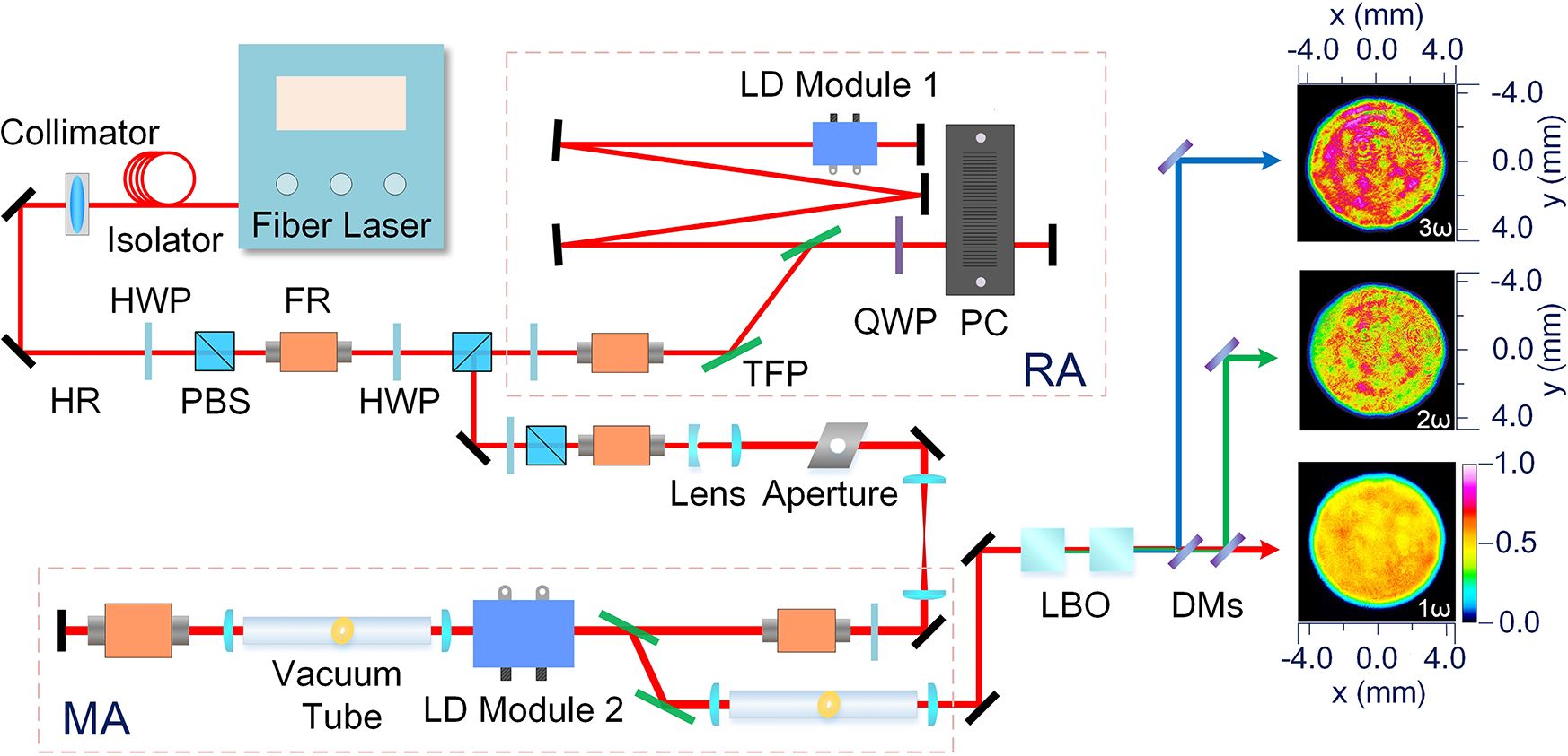
Figure 1 Schematic of the UV laser system and transverse beam profiles of the amplified pulses at 1064 nm (ω), 532 nm (2ω), and 355 nm (3ω) measured at their maximum energies via relay imaging. RA, regenerative amplifier; MA, main amplifier; HR, high reflector; HWP, half-wave plate; PBS, polarization beam splitter; FR, Faraday rotator; TFP, thin-film plate; QWP, quarter-wave plate; PC, Pockels cell; LD, laser diode; DM, dichroic mirror.
After the optical isolator, the laser pulse is injected into a beam shaper and amplified by a double-pass amplifier. The beam shaper consists of a beam expander with a plano-concave lens and a plano-convex lens that expand the Gaussian beam diameter to 12 mm. To achieve a high spatial filling factor, we used a specially designed 8 mm diameter soft-edge aperture that shapes the beam profile to a flat-top distribution, which matches the optical aperture of the amplification module in the double-pass amplifier. Beam quality was ensured using three image-relay Kepler telescopes, which consist of a 4f-based optical system with two plano-convex lenses to maintain a flat-top beam distribution after propagation with a 1:1 expansion ratio. The object plane of the 4f image-relay setup is at the soft-edge aperture, and the image planes are at the center of LD module 2, at the end mirror of the double-pass amplifier, and between the two nonlinear crystals in the harmonic generation unit, respectively. The beam shaping ensures that the amplified beam has a flat-top distribution for high-efficiency harmonic generation. After the beam shaping unit, the pulse energy is reduced to 3 mJ.
In the double-pass main amplifier (MA), LD module 2 with a 10 mm aperture can provide a small signal gain of 10 when operating at 100 Hz. However, as the Nd:YAG rod is side-pumped, the homogeneity of the amplification is dependent on the absorbance of the pumping light by Nd:YAG[Reference Noom, Witte, Morgenweg, Altmann and Eikema15]. To counter this, the five packaged LD submodules were distributed asymmetrically to ensure uniform pumping, and a circulatory water-cooling system was installed to maintain a steady LD module temperature and remove redundant heat to prevent fracturing of the gain crystal. The temperature of the water-cooling circulatory system was set to be stabilized at 27.5°C, which benefits the LD emission wavelength to match the absorption peak of the Nd:YAG crystal at 808 nm. The combined effect of the LD pumping and water-cooling systems was a non-uniform radial temperature distribution in the rod-shaped crystals, resulting in the Nd:YAG rod acting as a lens. To compensate for this thermal lensing effect, the second image-relay system was designed precisely so that the distance between the two plano-convex lenses was closer than what would normally be required. To prevent the laser pulses from ionizing the air at the focus, they are directed through a vacuum tube in the image-relay setup; furthermore, a pinhole set at the focal plane filtered the spatial high-frequency components to further maintain a flat-top beam distribution for the amplified beams. Thermal stress in the rod-shaped crystals resulted in a refractive index change because of the photoelastic effect, which led to thermally induced birefringence[Reference Su, Peng, Chen, Li, Wang and Leng16]. This birefringence can lead to depolarization and distortion of the output beam profile after passing through polarization-related devices[Reference Koechner and Koechner17]. When the laser beam travels through the same LD module and rod twice with a 90° polarization rotation, the radial and tangential polarizations also travel the same optical path length[Reference Lü, Kugler, Weber, Dong, Müller and Wittrock18]. To mitigate this effect, an FR was introduced to the double-pass configuration to achieve the polarization rotation while compensating for the thermal birefringence effect, resulting in laser beams that exited the TFP with flat-top near-field spatial profiles, as shown in Figure 1 (1ω). The energies of the laser pulses were boosted to 25 and 120 mJ after single- or double-passing LD module 2, respectively.
After passing through the third image-relay setup, the amplified pulses from the MA were injected into the harmonic generation unit, where two cascaded LBO crystals were employed to achieve THG. Both crystals were placed in constant temperature ovens to maintain stable temperature matching, and angular phase matching was achieved by their accurate alignment. The first LBO has an aperture of 12 mm × 12 mm and length of 10 mm and was cut at θ = 90° with φ = 11.3° for a type-I phase match. Up to 99.6 mJ, 532 nm laser pulses were obtained with 120 mJ injected laser energy at 1064 nm. Figure 1 (2ω) shows the near-field beam distribution of 532 nm laser pulses with 99.6 mJ energy. The second LBO crystal has a dimension of 12 mm × 12 mm × 15 mm and was cut at θ = 42.5° with φ = 90° for type-II phase matching. The spatial separation distance of these two LBO crystals is approximately 25 mm and focal lengths of the plano-convex lenses in the third Kepler telescope are both 280 mm. The energy ratio of the fundamental and the second harmonic laser pulses is approximately 1:2 for highly efficient frequency tripling, and the peak intensities of the 1064 nm and 532 nm beams are about 169.4 and 338.8 MW/cm2, respectively. Consequently, laser pulses at 355 nm were generated by SFG in the second LBO crystal and achieved an approximate flat-top near-field beam distribution at the maximum energy with spatial optimization, as shown in Figure 1 (3ω).
3 Results and discussion
Owing to the gain saturation effect of the Nd:YAG amplifier, the temporal width of the laser pulses was shortened after passing the MA; furthermore, because of temporal distortion during the amplification process, the temporal power density of the front edge was higher than that of the back edge of the output laser pulses, which resulted in a low filling factor and low THG conversion efficiency. Figures 2(a) and 2(b) show the time-domain waveforms of an unmodulated 1064 nm seed laser and the corresponding 355 nm laser, where the THG efficiency, without temporal optimization, was approximately 60%, which can be further improved by programming seed lasers in the time domain with the AWG. Because the length of the LBO crystal was designed to work at the average power density of laser pulses, high beam filling factors reduced the power density difference between each point of the laser beam and the corresponding average value; therefore, the peak power density of each point was at or close to the optimal value for THG, and a high triple frequency efficiency was achieved with a high spatial filling factor. In addition, the temporal distribution with a high filling factor is also the optimal distribution for high THG efficiency. To obtain amplified pulses with a high temporal filling factor, the fiber laser AWG was used to modulate the pulse duration and temporal shape of the seed laser. After optimizing the injection laser to have the same average amplified power, the amplified pulses were temporally flat-top to maintain a high filling factor, and modulated injection compensated for the temporal distortion of the laser pulses following amplification and THG, resulting in a temporal waveform output with a high 355 nm filling factor, as depicted in Figures 2(c) and 2(d). The resulting THG conversion efficiency from this temporal optimization was 76% from 1064 to 355 nm, which verified that a high filling factor is an important factor in this optimization process.
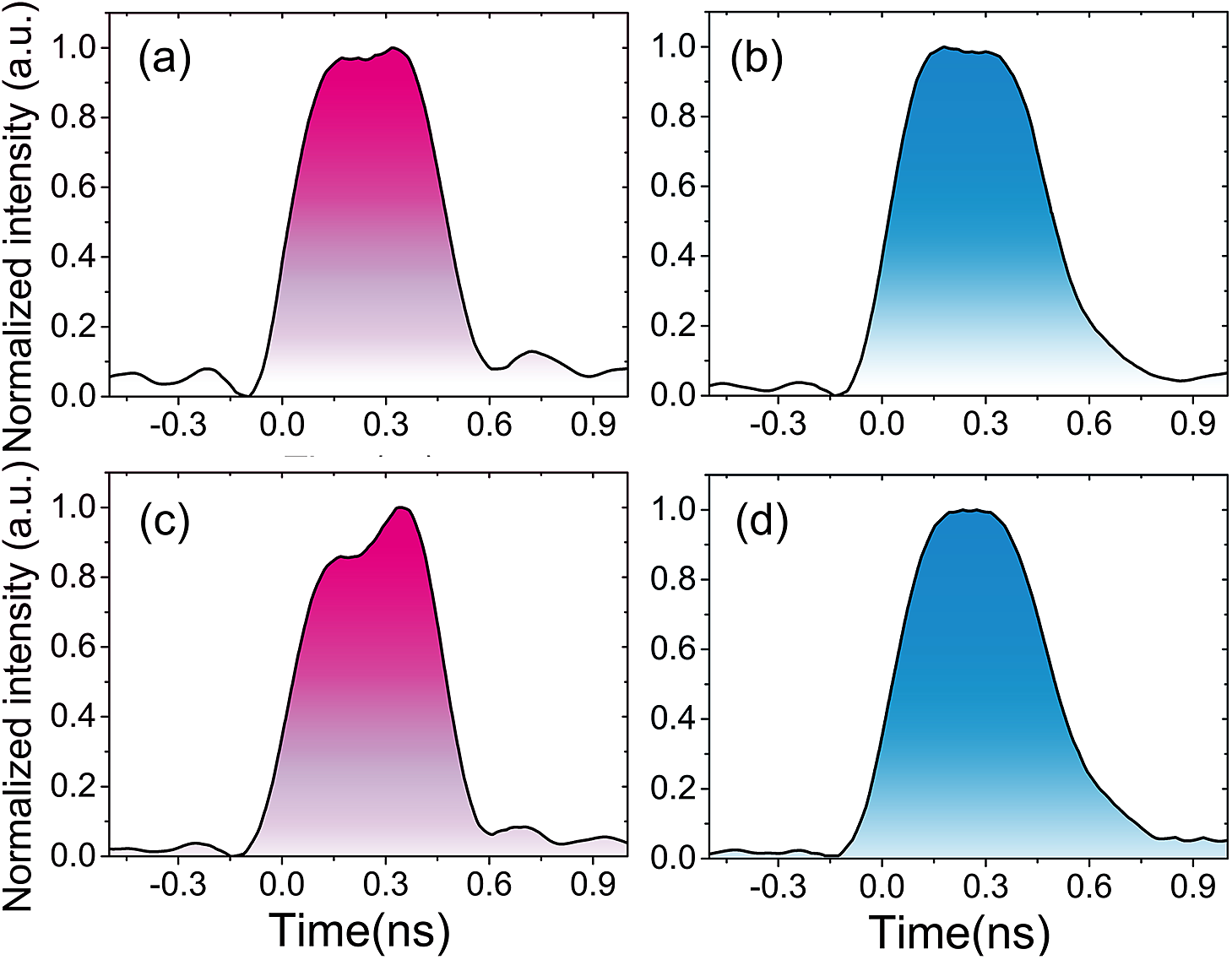
Figure 2 Time-domain waveforms of (a) an unmodulated 1064 nm seed laser pulse, (b) its corresponding 355 nm output, (c) a programmed 1064 nm seed laser pulse, and (d) its corresponding 355 nm output.
We measured the energy of 355 nm output pulses under seven different 1064 nm pulse width conditions, and Figure 3 shows the corresponding relationships between the THG conversion efficiency and measured 355 nm output pulse widths (FWHM). For each pulse width condition, the energy of the 1064 nm laser was also changed to maintain the same peak power density for THG. In addition, each seed laser injection was optimized to ensure that the 355 nm output retained a spatial and temporal flat-top distribution to keep a high filling factor for THG. As can be seen in Figure 3, the maximum THG conversion efficiency is 76% when the pulse width of the 355 nm laser was approximately 470 ps and the pulse width of the corresponding 1064 nm seed laser with spatial and temporal optimization was 500 ps.
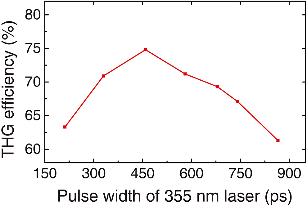
Figure 3 Relationship between THG conversion efficiency and the measured pulse width (FWHM) of the 355 nm output laser.
In order to evaluate the far-field beam quality of the UV laser after spatial and temporal optimization, encircled energy function of the two-dimensional integral for the diffraction-limit was deduced[Reference Clements and Wilkins19, Reference Stamnes, Heier and Ljunggren20]; however, the charge-coupled device (CCD) employed for beam diagnostics was a square pixel-type detector, so ensquared rather than encircled energy was utilized[Reference Andersen21]. Figure 4(a) shows the ideal ensquared energy of a focused flat-top beam and the actually measured ensquared energy of far-field laser beams, and Figures 4(b)–4(d) show the corresponding far-field beam profiles of 1064, 532, and 355 nm pulses measured at their maximum energies, respectively. These data demonstrate that the wavefront of the laser pulses distorts and the beam quality degrades a little during the nonlinear process. Spatial manipulation was effective at maintaining an approximate flat-top distribution for near-field 355 nm output beam profiles to achieve high-efficiency THG. In terms of the astigmatism, the far-field 355 nm output beam profile was close to that of the 1064 nm output with the vertical and horizontal directions in sharp focus at almost equal distances after spatial and temporal optimization.
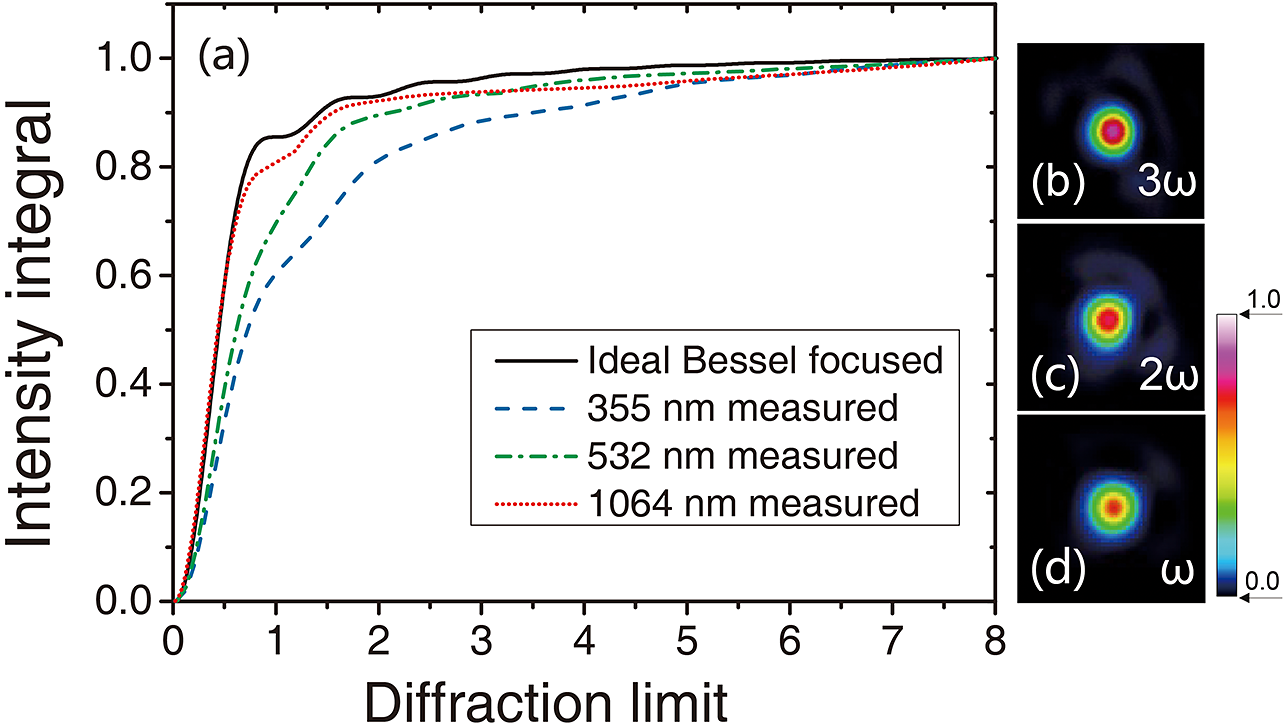
Figure 4 (a) Ideal ensquared energy of a focused flat-top beam and the actually measured ensquared energy of various far-field laser beams: (b) 355 nm, (c) 532 nm, and (d) 1064 nm measured at their maximum energies.
To improve the energy stability of the 355 nm output laser pulses, we controlled the stabilities of the time-domain waveforms of laser pulses and temperatures of the two LBO crystals. When the DPSSL system was operated at a wavelength of 1064 nm and 100 Hz repetition rate with a 120 mJ pulse energy and 500 ps duration (FWHM), the energy stability within 3 h was 0.82% (RMS), as can be seen in Figure 5. In addition, following spatial and temporal optimization, laser pulses at a wavelength of 355 nm and 470 ps width (FWHM) were generated with 91 mJ energy, and the energy stability in 3 h was 1.07% (RMS), as shown in Figure 5. The temperature stability relaxation of the LBO crystals also caused the periodic fluctuation of the energy stability of the 355 nm lasers.
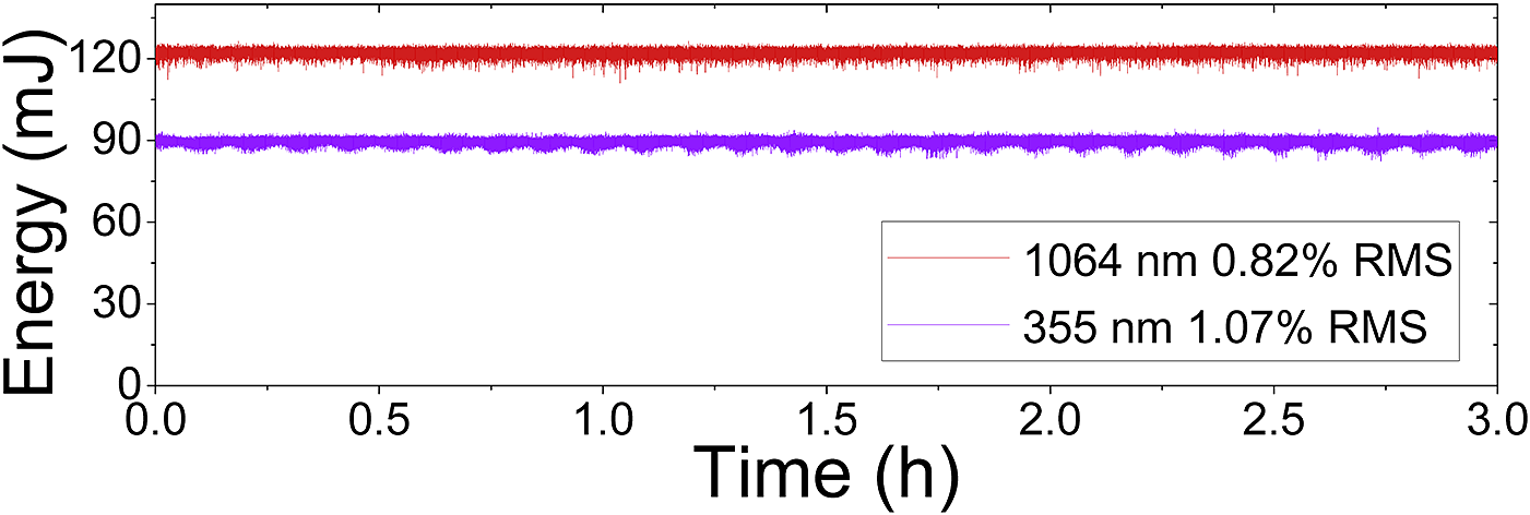
Figure 5 Energy stability of 1064 nm and 355 nm laser pulses.
4 Conclusions
In summary, using spatial and temporal manipulation techniques, we have demonstrated a high-energy, high-repetition-rate stabilized picosecond UV laser with an enhanced THG conversion efficiency, which delivered 91 mJ pulses with a duration of 470 ps at a frequency of 100 Hz. The 355 nm laser pulses were generated from a 120 mJ 1064 nm picosecond MOPA-based DPSSL and subsequent LBO crystal-based THG system. The 1064 nm DPSSL featured a flat-top spatial and temporal distribution and 0.82% (RMS) energy stability within 3 h. Spatial modulation devices, including a soft-edge aperture, image-relay setup, FR, and spatial filter, were used to maintain a high spatial filling and correspondingly high THG conversion efficiency. Consequently, spatial gain distortion, thermal lensing, and depolarization effects were effectively compensated for, which resulted in a high-power laser beam output with a flat-top spatial distribution. Moreover, through high-precision temporal waveform modulation and accurate phase matching to improve the temporal filling factor of the UV laser, we were able to achieve an extremely high THG efficiency of 76% with a 355 nm pulse width of 470 ps (FWHM). To the best of the authors’ knowledge, this is the highest THG conversion efficiency in a high-power, high-repetition-rate picosecond solid-state laser. In addition, following spatial and temporal optimization, the far-field 355 nm beam output profile was close to that of the 1064 nm beam, and the energy stability within 3 h of the 355 nm pulses was 1.07% (RMS) operating at 91 mJ. We consider this high-energy, high-repetition-rate picosecond UV pumping laser system to be an attractive pumping source for a wide variety of applications.
Acknowledgments
This work was supported by the National Natural Science Foundation of China (61925507 and 62075227), National Key R&D Program of China (2017YFE0123700), Strategic Priority Research Program of the Chinese Academy of Sciences (XDB1603), Program of Shanghai Academic/Technology Research Leader (18XD1404200), Shanghai Municipal Science and Technology Major Project (2017SHZDZX02), and Youth Innovation Promotion Association CAS (2020248).


