


Introduction
The turbomachinery industry is witnessing rapid innovation, with a significant impact on the design process, to respond to the demands of the new energy transition markets. To meet these needs, energy companies are redesigning their products at a rapid pace, often using a multi-disciplinary design process that includes parametric CAD modeling, finite element structural analysis (FEA), computational fluid dynamics (CFD), and thermodynamics. A key aspect of this process is that many turbomachinery companies adopt an engineering-to-order (ETO) production approach, which is one related to all the companies that are involved in the design and production of customized products such as construction projects, shipbuilding, and machine tools (Cannas and Gosling, Reference Cannas and Gosling2021), which requires a short lead time for early design activities after receiving a customer request. These activities often involve iterations of calculations and multi-objective design analyses that rely on data and constraints that are not fully known at the outset and are often led by human designers. As a result, the traditional trial-and-error design method, which significantly relies on the experience of design engineers (DEs), is time-consuming and may not lead to globally optimized designs (Li and Zheng, Reference Li and Zheng2017). Indeed, the design process may last weeks or months, while the customer’s request may have to be fulfilled in a few days.
ETO refers to customized products developed or adapted to meet customer specifications (Gosling and Naim, Reference Gosling and Naim2009). This process often involves the customer participating in the design phase and can lead to coordination issues in terms of integrating engineering and production (Mello et al., Reference Mello, Strandhagen and Alfnes2015). To streamline their internal processes and improve efficiency, ETO engineering companies must look for ways to automate the engineering phase as much as possible, particularly considering the market’s demand for reduced errors and delays. From this perspective, a system-level configurator approach can support DEs in delivering a quick solution, while the details related to the uncertainties of the design configuration changes remain unspecified (Kristianto et al., Reference Kristianto, Helo and Jiao2015). ETO products are found in various industries, including mechanical engineering, construction, and shipbuilding. There are several archetypes of ETO products based on volume and the amount of order-specific engineering work needed (Willner et al., Reference Willner, Powell, Gerschberger and Schönsleben2016b). Customers in the ETO sector often demand short lead times and are unwilling to pay high price premiums (Tu, Reference Tu1997), which can create challenges for companies in terms of meeting customer demands while also conducting order-driven design and engineering activities (Gosling et al., Reference Gosling, Towill, Naim and Dainty2015). The engineering design process in ETO may involve both repetitive and creative tasks (Verhagen et al., Reference Verhagen, Bermell-Garcia, Van Dijk and Curran2012) and often requires the use of product structures that distinguish between reusable standard components and configurable components that are engineered for a specific order (Brière-Côté et al., Reference Brière-Côté, Rivest and Desrochers2010). There are many terms used in the literature to describe these various components of ETO products, including:
-
• modular design (Baldwin and Clark, Reference Baldwin and Clark2000): ‘a module is a unit whose structural elements are powerfully connected among themselves and relatively weakly connected to elements in other units’,
-
• platform designs (Simpson et al., Reference Simpson, Maier and Mistree2001): a design driven by a ‘set of parameters (common parameters), features, and/or components that remain constant from product to product, within a given product family’,
-
• parametric design (Wielinga and Schreiber, Reference Wielinga and Schreiber1997). ‘Characteristic for parametric design is that essentially all relevant knowledge is expressed as mathematical constraint expressions over design parameters. A parametric design problem is given by an input set of requirements and constraints, but such that these can be converted into a set of value or value range assignments of parameters’.
All of the aforementioned features have been thoughtfully incorporated into the content of this article, with a particular focus on the comprehensive examination of the current state-of-the-art in the dedicated section.
Design automation (DA) tools are extensively used in the industry to increase product competitiveness and company productivity. In this context, the work by Willner et al. (Reference Willner, Gosling and Schönsleben2016a) aims to investigate DA in the ETO sector from a maturity perspective. Among the different studies on this topic, knowledge-based engineering (KBE) is reported to be one of the core DA subdisciplines for ETO purposes. It also provides a step-by-step guide for companies on how to use DA to gain a competitive advantage in their sales and delivery processes. In turn, it contributes to understanding how DA can be effectively implemented in the ETO sector and offers practical recommendations for companies intended to adopt this technology. One limitation emerging from this study is the exclusion of DA in new product development processes.
The application of KBE for DA processes offers benefits such as standardization, error reduction, and shortened lead times, particularly in the early design stage (Ascheri et al., Reference Ascheri, Furini, Colombo, Atzeni and Ippolito2016) but also in terms of efficiency in product manufacturing and in repetitive tasks (Lindholm and Johansen, Reference Lindholm and Johansen2018). However, the different methods for enabling DA processes lead to choosing from and interactively working with automatically generated alternative solutions (Entner et al., Reference Entner, Prante, Vosgien, Zavoianu, Saminger-Platz, Schwarz and Fink2019), and this could be seen as a limitation to be taken into account when dealing with complex systems in the ETO industry, as it may not allow sufficient flexibility of components design. High-level 3D CAD configurators (Raffaeli et al., Reference Raffaeli, Mengoni and Germani2013) and master models (Frank et al., Reference Frank, Entner, Prante, Khachatouri and Schwarz2014) can provide a central product model that includes all necessary information for the various engineering disciplines involved in the design process, eliminating the need for separate disciplinary models. However, working with complex systems of components can result in a large number of input variables, which can pose challenges for configuration change management if the model is not constructed or fed correctly. In addition, the design space may be limited to certain morphological transformations, such as gas path layout in turbomachinery, as needed in ETO-structured companies.
To address the research gaps in the ETO industry, this work, conducted in collaboration with the engineering department of Baker Hughes (BH), an energy company playing in Oil & Gas and energy transition markets, focuses attention on the design process of API 618 BH reciprocating compressors (RCs) (API Standard 618, Fifth edition, December 2007) as a means of study to develop and validate the methodology proposed in this paper. In particular, this research focuses on RC cylinders, which are the core of the compression, where their parameters and characteristics affect the overall performance of the machine.
The as-is design process for non-standard RC cylinders is mainly human-driven and embeds several iterations to reach the desired configuration, starting from a preliminary sizing of the machine through thermodynamic and mechanical calculation tools, passing through preliminary modeling which usually requires structural and fluid-dynamic verifications with CAE technologies. Final checks have to be performed to freeze the optimal configuration of the whole machine.
This work aims to improve the design process by focusing on customer needs for optimal design solutions (in terms of absorbed power and flow rate processed by the machine) and reduced lead time. With this purpose, we propose an integrated data analysis process in this paper that incorporates advanced DA master models capable of managing non-routine design configurations. Indeed, the industrial necessity here is to meet stringent design process deadlines by providing a sufficiently accurate solution to the customer in terms of absorbed power (and flow rate processed by the machine) with limited computational resources, as already analyzed by Batini et al. (Reference Batini, Becattini and Cascini2023). The proposed process assumes that, among the different methods available in the engineering field to goal a first-tentative target solution, artificial neural networks (ANNs) can provide optimal RC cylinder designs in terms of predictive capacity and computational time compared to more computationally expensive optimization methods such as CFD (Nakano and Kinjo, Reference Nakano and Kinjo2008).
This research introduces a novel, integrated method that leverages ANNs to enhance the design process in the highly complex and customized ETO sector, specifically for turbomachinery systems. While ANNs have been used in various engineering applications, our work uniquely applies it to address the challenges of product customization, short lead times, and cost efficiency in ETO production. The core innovation lies in the integration of ANN with a multi-objective optimization framework that enables simultaneous optimization of multiple conflicting design parameters. This method not only reduces the traditional engineering cycle time but also facilitates the dynamic adaptation of designs to meet specific customer requirements, which is a critical bottleneck in ETO industries. By embedding the above-mentioned tools in the customization processes, our approach takes a step ahead toward DA. This aims at significantly improving resource allocation and production efficiency, offering a scalable solution for industries where product designs must be tailored for each order. The combination of ANNs and an optimization routine presents a novel contribution thanks to their integration within DA processes, enabling manufacturers to deliver tailored, high-quality products faster and at lower costs, making it especially impactful in the rapidly evolving energy transition markets.
The research presented in this article analyzed a database of the 365 cylinders available in the BH fleet, embedding the values of the parameters affecting the machine’s performance obtained through CFD analyses performed during the past years. It represents the design space of existing cylinder families, and ANNs may be beneficial in constructing a surrogate model of the problem, as BH is pushing for the implementation of artificial intelligence through ANNs where big data is available. Moreover, ANNs can be advantageous because they can provide accurate predictions without the computational expense of other numerical methods when a large and heterogeneous database is available.
Overall, this paper aims at answering the following research questions (RQs):
-
1) What are the ANN-based approaches, methods, and tools in the literature related to the turbomachinery industry that enable DA processes in the context of an ETO-structured company?
Based on these findings, we defined a workflow and a tool pipeline to improve the development of a new RC cylinder design at BH, taking into account its available resources. Consequently, the second RQ follows:
-
2) What are the benefits that the proposed integrated approach brings to industrial practice?
This paper is structured as follows. Section “Related work and state-of-the-art” summarizes the state of the art and highlights the research gaps we aim to fill. Section “Research methodology” outlines the methodological approach adopted for the research development and the choices made for its purpose. Section “Integrated DA process” presents the original DA workflow and tools pipeline to support DEs in delivering an optimal design configuration of the studied system. In Section “Computational pipeline applications”, several case studies taken from the BH portfolio are presented to measure the performance of the integrated method. Finally, Sections “Results and discussion” and “Conclusions and future perspectives” summarize the results of this work and its scientific contribution and propose future perspectives of this research while discussing its limitations.
Related work and state-of-the-art
A literature review has been carried out to answer RQ1 and is summarized in this section. In this context, the literature is well consolidated and provides valuable information on the functionality, performance, limitations, and constraints of different methods and tools.
DA in ETO processes: managing engineering changes in configuration
DA is largely discussed in the literature. In this paper, we adopt the definition of DA by Cederfeldt and Elgh (Reference Cederfeldt and Elgh2005): ‘computerised automation of tasks that are related to the design process through the implementation of information and knowledge in tools or systems’. There is a significant amount of literature on the technical aspects of DA, but there is relatively little literature on its applications in the ETO industry. Researchers have proposed recommendations for planning design automation in ETO companies, including an information model for design automation in quotation preparation (Elgh, Reference Elgh2012) and the need for a design automation framework based on a study with ETO manufacturers (Cederfeldt and Elgh, Reference Cederfeldt and Elgh2005).
According to Haug et al. (Reference Haug, Ladeby and Edwards2009), transitioning from ETO to mass customization involves considering five critical dimensions for determining the appropriate level of standardization and automation: product variety, customer perception, manufacturing costs, business objectives, and configurator challenges. These dimensions vary based on the challenges and disparities between mass producers and ETO companies during the transition to mass customization (Davis, Reference Davis1987). In the context of mass producers, fostering product variety is essential, whereas ETO companies need to adopt limitations in this aspect. From a customer’s perspective, customization must offer tangible value; otherwise, it may lead to disorientation. Although customization typically incurs higher manufacturing costs, effective management can keep prices comparable to mass-produced products. The primary purpose of adopting mass customization is to boost sales. Customers in mass-production companies have more limited design choices than ETO companies, where configurator design is crucial. Conversely, ETO companies face the main challenge of finding the right balance between design flexibility and standardization. In turn, Haug et al. (Reference Haug, Ladeby and Edwards2009) suggest that during the transition to mass customization, careful consideration of these five dimensions is pivotal to successful implementation and adaptation to the specific needs of both mass producers and ETO companies.
DA for highly customized ETO products typically involves developing and implementing IT applications such as sales (Hvam et al., Reference Hvam, Pape and Nielsen2006) and engineering configurators (Mäkipää et al., Reference Mäkipää, Paunu and Ingalsuo2012), as well as linking them with CAD systems (Raffaeli et al., Reference Raffaeli, Mengoni and Germani2013). While product lifecycle management (PLM) systems are often seen as enabling the sharing of product data across supply chains or product lifecycles (Silventoinen et al., Reference Silventoinen, Pels, Kärkkäinen and Lampela2011), their effectiveness in ETO environments is still uncertain (Hicks and McGovern, Reference Hicks and McGovern2009). Standard and configurable components, common in make-to-order (MTO) products (Lee and Lee, Reference Lee and Lee2014), can be stored and retrieved for reuse with various IT applications. However, these approaches do not adequately address the unique requirements of ETO environments, such as the need for creative design tasks for order-specific solutions (Zhang, Reference Zhang2014). There have been some efforts to address the challenges of design automation in ETO environments, including proposals for a product structure concept that promotes the reuse of order-specific solutions (Brière-Côté et al., Reference Brière-Côté, Rivest and Desrochers2010) and the development of a system-level configurator that handles incomplete configurations and engineering changes (Kristianto et al., Reference Kristianto, Helo and Jiao2015). Design automation in ETO processes has several limitations that can impact the efficiency and effectiveness of the engineering process. Some of the main limitations emerging from the literature are:
-
• Complexity: ETO processes often involve complex products that require a high level of customization, which makes it challenging to automate the design process (Thomassen and Alfnes, Reference Thomassen and Alfnes2017). The complexity of the product may require specific engineering expertise. Indeed, the externalization of tacit knowledge (Yi, Reference Yi2006) cannot be easily automated, making it difficult to apply DA;
-
• Lack of standardization: due to the high level of customization needed, ETO processes typically lack standardization, which makes it difficult to automate the design process. The lack of standardization may require manual intervention, resulting in increased engineering time and costs (Haug et al., Reference Haug, Ladeby and Edwards2009);
-
• Interdisciplinary collaboration: DA often requires collaboration across different disciplines. Collaboration across these disciplines can be difficult to automate and requires careful coordination to ensure that all aspects of the design are integrated correctly (Heikkinen et al., Reference Heikkinen, Johansson and Elgh2020). In general, it may be necessary to implement dedicated methodologies to make explicit the DA processes (Curran et al., Reference Curran, Verhagen, Van Tooren and Van Der Laan2010), particularly when an ETO production approach is adopted by a company (Bakker et al., Reference Bakker, Boehme and van Donk2012);
-
• Customer requirements: ETO processes are driven by customer requirements, which can vary significantly, and meeting these requirements often requires manual intervention to ensure that the design meets the customer’s needs (Cederfeldt, Reference Cederfeldt2007).
Overall, design automation can be challenging in ETO processes due to the high level of customization needed and the need for interdisciplinary collaboration and accurate data management. Furthermore, the current state of DA in ETO is limited, and further research is required in order to address these environments’ unique challenges and requirements.
Methods and tools that can enable DA in ETO processes
The limitations presented in Section “DA in ETO processes: managing engineering changes in configuration” can be addressed through methods that find optimal designs by means of techniques that do not rely on predetermined solutions (Amadori et al., Reference Amadori, Tarkian, Ölvander and Krus2012) and could support DA processes in dealing with ETO constraints and multi-objective function design problems.
Among the strategies that address these needs, some methods use randomized fluctuations in the design variables, such as genetic algorithms (GAs) (Forrest, Reference Forrest1996), while others avoid the direct adjustment of design variables entirely by employing learning algorithms (Sobieszczanski-Sobieski et al., Reference Sobieszczanski-Sobieski, Morris and Van Tooren2015).
Machine learning (ML) techniques are used to teach machines how to handle data more efficiently (Mahesh, Reference Mahesh2020). In this context, the work of Eichhoff and Roller (Reference Eichhoff and Roller2015) includes a review of ML approaches to support configuration and parameterization in design exploration and optimization through the elaboration of information and relationships. ML relies on different algorithms to solve problems of diverse nature, such as supervised learning (Cunningham et al., Reference Cunningham, Cord and Delany2008), unsupervised learning (Barlow, Reference Barlow1989), semi-supervised learning (Reddy et al., Reference Reddy, Viswanath and Reddy2018), instance-based learning (Kramer, Reference Kramer2013) and ANNs, which are a type of ML algorithm inspired by the structure and function of the human brain. They consist of layers of interconnected “neurons” that can process and transmit information. ANNs can be trained to recognize patterns and make decisions based on input data. They are commonly used for tasks such as image and speech recognition, natural language processing, and predictive modeling (Bishop, Reference Bishop1994). ANNs implement algorithms that aim to achieve neurological-related performance through a group of multiple perceptrons or neurons at each layer. Their history began in the early 1940s, and they historically have been used for engineering control systems (Meireles et al., Reference Meireles, Almeida and Simões2003) and other engineering industrial problems where physical processes are not well understood or are highly complex, with uncertainties that justify their utilization (Fukuda and Shibata, Reference Fukuda and Shibata1992).
One of the possible benefits of using ANNs in DA processes for ETO purposes could be their ability to process large amounts of data quickly (Woldemariam and Lemu, Reference Woldemariam and Lemu2019). This can be particularly useful when it is difficult to identify a suitable a priori design optimization model. However, one limitation of ANNs is that they may not perform well when faced with inputs significantly different from those used in the training phase. This can be especially problematic when trying to extrapolate results beyond the training inputs’ range, as Bishop (Reference Bishop1994) pointed out. In these cases, the network may not respond accurately to the new inputs, leading to unreliable results.
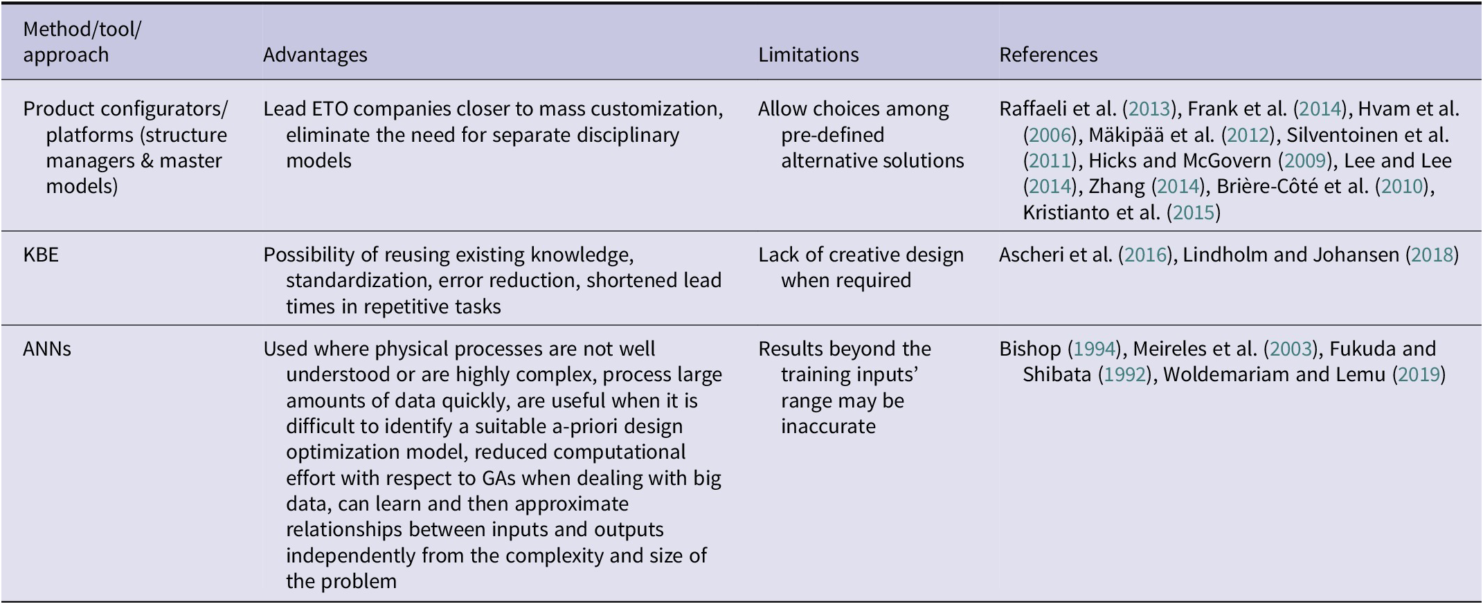
Table 1 summarizes the approaches used to address the challenges of DA processes in the ETO industry.
Table 1. Approaches that can support DA processes in the ETO industry
In this research, we propose an integrated method that utilizes ANNs to reduce the need for massive simulations in the design process and to suggest an optimized design configuration in the ETO sector, specifically for complex turbomachinery systems. Unlike new product development (NPD) environments, where active exploration of entirely new design spaces is common (Takeuchi and Nonaka, Reference Takeuchi and Nonaka1986), ETO involves the customization of existing products to meet specific client requirements. In this context, there is often a wealth of historical data from prior designs and simulations, allowing us to build a robust ANN model using pre-existing CFD simulations. This approach reduces engineering cycle times and enables rapid optimization of multiple conflicting design parameters (Zhou and Ooka, Reference Zhou and Ooka2021). The novelty of our work lies in the integration of ANNs – as an enabler – within DA processes specifically tailored for the ETO sector, where the focus is on adapting and optimizing designs quickly, as opposed to creating entirely new configurations from scratch.
We acknowledge that active learning approaches, such as Bayesian optimization (Shahriari et al., Reference Shahriari, Swersky, Wang, Adams and De Freitas2015) and Gaussian process models (Tyagi et al., Reference Tyagi, Yang, Tyagi and Dwivedi2011), could further reduce the reliance on large datasets by selectively generating new data points as needed, particularly when working in new or unexplored design spaces like in the case of NPDs (Bae et al., Reference Bae, Nam and Kang2024). However, our current approach is tailored to environments where a significant amount of simulation data is already available, as the case in ETO applied to turbomachinery industry typically is.
In the following subsection, a deeper literature review on ANNs has been carried out, focusing on applications in the turbomachinery industry that have been used as a starting point for this work and whose limitations we tried to overcome, as we assumed of using ANNs for enabling DA processes in the ETO industry.
A focus on ANNs: a metamodel for the turbomachinery industry
In order to reduce the number of expensive simulation calls during the optimization of problems like the one presented in this paper, surrogate models are generally employed (Wu et al., Reference Wu, Sotnikov, Gary Wang, Coatanea, Lyly and Salmi2023). Historically, simulation metamodeling is commonly performed through ANNs (Fonseca et al., Reference Fonseca, Navaresse and Moynihan2003). Many different types of neural network models have been developed over the years, but among the most common in industrial applications are the multilayer perceptron (Gardner and Dorling, Reference Gardner and Dorling1998) and the radial basis function network (Orr, Reference Orr1996). These two methods are the foundation of many practical applications (see the review of Meireles et al., Reference Meireles, Almeida and Simões2003) and are of particular interest in this work. They belong to a general class of neural networks known as feed-forward networks (Bebis and Georgiopoulos, Reference Bebis and Georgiopoulos1994), which have been the subject of extensive research in recent decades (Abdolrasol et al., Reference Abdolrasol, Hussain, Ustun, Sarker, Hannan, Mohamed and Milad2021). Feed-forward networks are the most popular type of neural network algorithm in engineering applications (Wu and Wang, Reference Wu and Wang2021), thanks to their ability in learning patterns and relationships directly from data, making them suitable for optimization tasks where the underlying physics is complex or not fully understood (Edlan and Shamir, Reference Eldan and Shamir2016). By training on relevant data, feed-forward networks can uncover intricate interactions between design parameters and performance metrics, leading to improved optimization results (Xu et al., Reference Xu, Liu, Cao, Huang, Liu, Qian and Zhang2021). A feed-forward neural network can be considered a non-linear function that transforms input variables into a set of output variables through a series of hidden layers (cfr. Figure 1). Each hidden layer (see the layer where D and E are in Figure 1) is a layer between the input (A, B, C) and output (F) layers that performs the transformation between weighted inputs and outputs using a set of parameters (weights) determined through a learning or training process (Wu and Wang, Reference Wu and Wang2021).
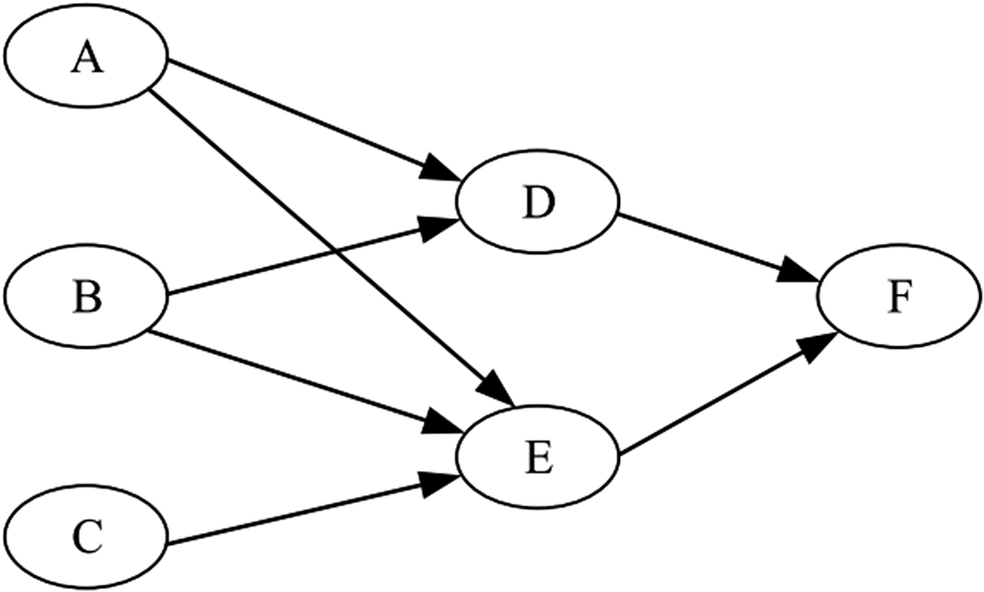
Figure 1. Structure of a feed-forward neural network, as schematized by Wu and Wang (Reference Wu and Wang2021).
This process can be computationally intensive, but once the weights have been determined, the network is able to process new data quickly. The training phase of a neural network involves adjusting the weights to produce the desired responses. The goal of any learning algorithm is to find the values of the weights that minimize an appropriate error function (Bishop, Reference Bishop1994).
ANNs have been widely used in the turbomachinery industry for simulations and predictions of the performance of various components, such as gas turbines (Lazzaretto and Toffolo, Reference Lazzaretto and Toffolo2001), axial compressors (Yu et al., Reference Yu, Chen, Sun and Wu2007), and centrifugal compressors (Ghorbanian and Gholamrezaei, Reference Ghorbanian and Gholamrezaei2009; Jiang et al., Reference Jiang, Dong, Liu, He and Ai2019). Nevertheless, these applications often tend to concentrate solely on the performance of individual components, disregarding the potential impact that variations in internal design parameters may have on overall performance. Ghorbanian and Gholamrezaei (Reference Ghorbanian and Gholamrezaei2007) conducted a comparison between several types of ANNs for simulating the performance of axial compressors and demonstrated that some of them deliver results aligned with experimental data. In recent years, ANNs have also been utilized for optimizing the layout of turbomachinery components (Du et al., Reference Du, Li, Yang, Liu, Zhang and Xie2022) and for design optimization as a surrogate model to reduce computational efforts, with respect to more robust optimization methods (i.e., GA), when a large amount of data is available (Woldemariam and Lemu, Reference Woldemariam and Lemu2019). Applications have been conducted on centrifugal impellers (Ji et al., Reference Ji, Wang, Tang and Xi2021), radial turbines (Luczynski et al., Reference Luczynski, Hohenberg, Freytag, Martinez-Botas and Wirsum2021), and fan blades (Lopez et al., Reference Lopez, Ghisu and Shahpar2022). Similar to the abovementioned papers, these applications mainly focus on the shape optimization of single components and do not involve complex systems studies.
Derakhshan et al. (Reference Derakhshan, Mohammadi and Nourbakhsh2010) proposed a comparison between GAs and ANNs to optimize the shape of the radial blade. In both these cases, the analysis focuses on a single component.
ANNs represent an alternative computational approach in which the solution to a problem is derived from a set of samples rather than relying on explicit instructions as in traditional calculation methods. In this context, one of the main advantages of using ANNs in advanced DA models is the ability to quickly process large amounts of data (Rojas, Reference Rojas2013). Furthermore, ANNs can learn and then approximate relationships between inputs and outputs independently from the complexity and size of the problem (Haykin, Reference Haykin2004). However, a disadvantage of ANNs is that they may not perform well when faced with inputs significantly different from those used during the training phase or when attempting to extrapolate results to regions where the inputs are substantially different from those used in the training phase (Bishop, Reference Bishop1994).
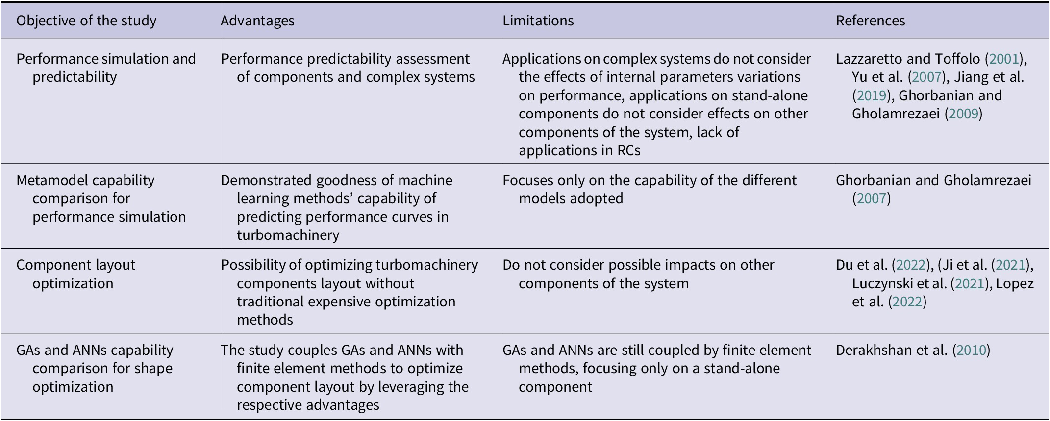
A summary of ANN-based approaches that have been reviewed is shown in Table 2, according to the objective of the related study to highlight their advantages and limitations from the perspective of their potential in DA processes.
Table 2. ANN-based approaches in the ETO turbomachinery industry and the related potential for supporting DA
In this section, a literature review has been carried out to highlight the DA models adopted in design processes in ETO-structured companies. The ANN-based tools and methods used in the turbomachinery industry that can enable DA processes in the ETO industry have been outlined to answer RQ1.
Limitations and research gaps have been highlighted to ensure the robustness of the design process of BH RC cylinders. The methodology proposed in the following sections aims to guarantee both the repetitiveness of the task and the possibility of customizing the product by meeting the lead time needed by the customer. Overall, from the literature review, it emerges that the integrated approach combining ANNs and DA methods for RC cylinder design has the potential to generate significant benefits in industrial practice, including improved design efficiency, enhanced performance, cost reduction, knowledge generation, and a competitive advantage in the turbomachinery industry. In the following sections, the methodological approach and the integrated DA method that constitute the main original contribution of this work will be presented and validated through real job applications to answer RQ2.
Research methodology
This section outlines the methodological approach adopted throughout this research. First and foremost, it is essential to address the critical issues associated with the non-routine design of RC cylinders within the ETO industrial framework. An in-depth examination was conducted, focusing on a case study: a project undertaken in recent years that entailed the complete inception and development of an RC Cylinder for a specific service application. This analysis highlighted the criticalities due to the lack of a systemic approach in developing a new design of this type. This involved several iterations both in design implementation and information exchange within the company that implied unacceptable lead time in delivering the solution required by the customer.
The acquired data were subsequently consolidated by integrating it with insights from literature and BH internal documentation. Following this comprehensive review, we pinpointed the research gaps related to the general design process of complex systems involving turbomachinery components and, in particular, RC cylinders within the ETO industry.
In particular, the current process for designing non-standard RC cylinders (cf. Figure 2) is primarily human-driven and requires multiple iterations to meet job requirements. First, a thermodynamic and mechanical calculation delivers a preliminary overall configuration of the machine, with a general layout provided by BH computational tools mainly run by Application Engineers (AEs), shown as “Calc26” in the figure. Then, a preliminary 3D modeling of the cylinders that must be redesigned is developed by DEs. Iterations of 3D modeling and numerical simulations (CFD and FEA where needed) are necessary to reach the final configuration that allows the cylinder to meet the customer’s requirements. Finally, the overall model of the machine must be validated to freeze the final configuration, otherwise additional iterations may be needed.
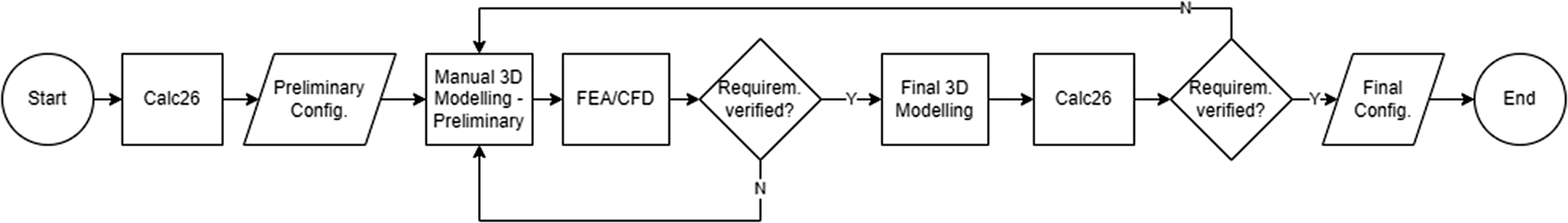
Figure 2. As-is design process of non-standard BH RCs cylinders.
Building upon these identified gaps, we formulated the RQs presented in Section “Introduction”. We decided to employ ANNs as a tool enabling an integrated DA process. This choice was made after an analysis of the database available in BH repositories summarizing the geometrical and performance properties of the cylinders fleet and a thorough examination of various approaches involving ANNs in the context of DA processes within the ETO industry, as presented in the literature and summarized in Section “Related work and state-of-the-art”, to answer RQ1.
The core of this research involves the development of an integrated process suitable to deliver a first-tentative optimal design solution of a complex system of turbomachinery components, from the customer requirements to the embodiment design, using BH RC cylinders as a case study. First, a DA master model embedding a knowledge-based 3D model was developed to manage different cylinder configurations. Then, ANNs have been trained by exploiting the existing database. Finally, ANNs have been integrated in the process thanks to a tool used as an enabler for DA. The details of the integrated DA method are outlined in Section “Integrated DA process”.
The final part of the research project summarized in Section “Computational pipeline applications” has been the validation of the process carried out on three different representative case studies of BH RCs cylinders. For each of these cases, the complete computational pipeline has been tested by applying the integrated method.
The benchmark at BH for computing RC cylinders’ performance is CFD analysis. Therefore, we decided to compare the results of the integrated DA method with those obtained by CFD simulations performed on the final configurations of the cylinders obtained with the proposed design process. The Key Performance Indicators (KPIs) allowing to evaluate the quality of the proposed integrated method are:
-
• Functional performance refers to the accuracy of the output in terms of error with respect to the benchmark results (i.e., CFD analysis);
-
• Total lead time needed to provide the optimised solution to the customer compared to standard CFD analysis.
The details of KPI values and their role in answering the RQs are outlined and explained in Section “Results and discussion”.
Integrated DA process
This section presents the development of the integrated method to achieve the desired configuration of an RC cylinder when a non-routine design is required by the customer.
Overview of the proposed process
The proposed method converts input variables given by the customer, such as flow rate and gas composition, into an optimized and validated cylinder configuration, thanks to the integration within the same process of DA methods and tools specifically embedded for this purpose.
The proposed method is schematized in Figure 3 using the IDEF0 model (Presley and Liles, Reference Presley and Liles1995). The arrows on the left summarize the inputs, the ones from the top represent the rules, the constraints, and the models, and the ones from the bottom represent the resources, while the arrow on the right of the block represents the output of the method.
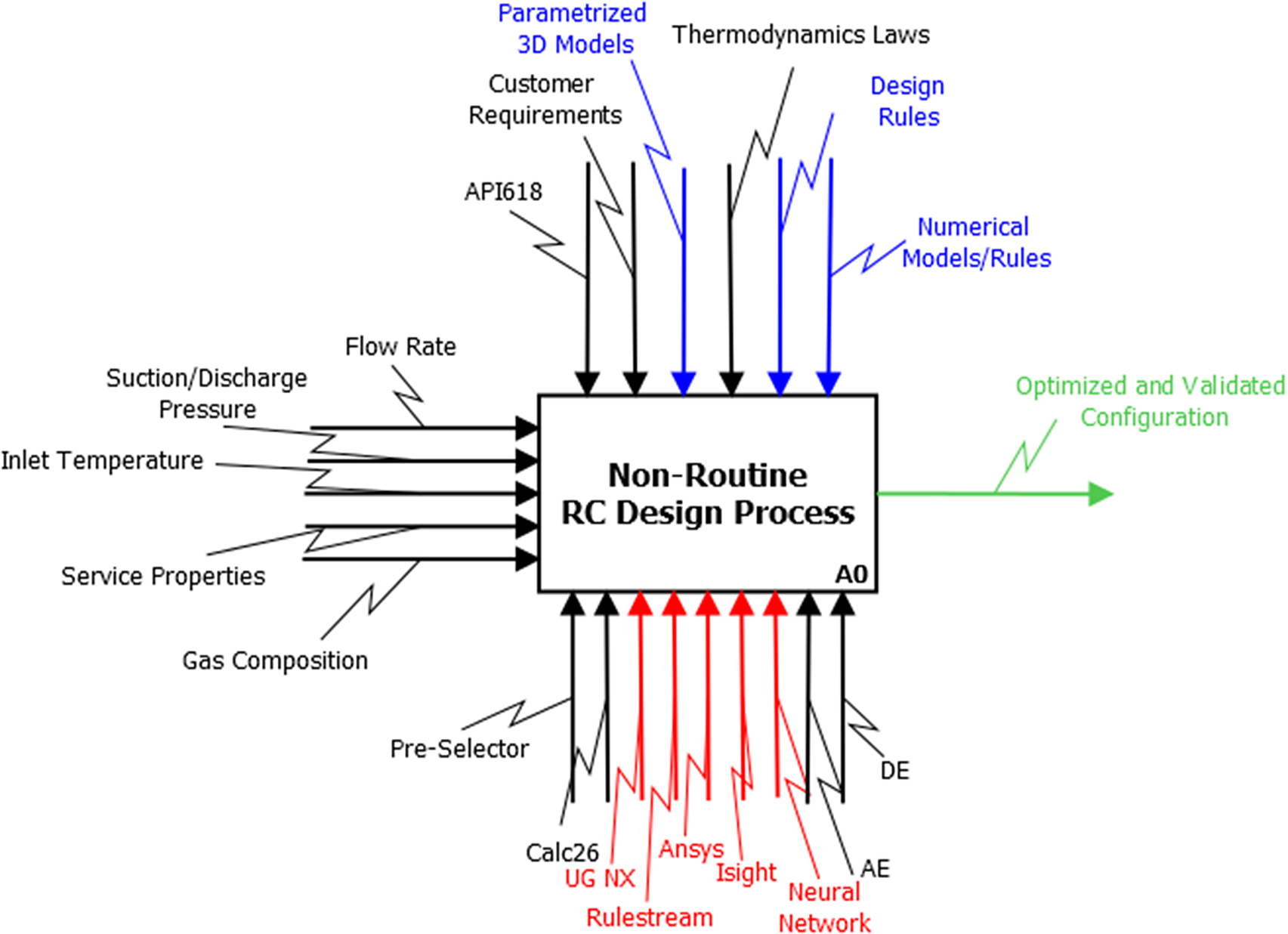
Figure 3. Level 0-IDEF0 representation of the new RC cylinder design development process.
In Figure 3, the black lines represent the flows that already exist in the design process of RC cylinders described in Section “Research methodology” (cf. Figure 2). Blue lines mark the new models and rules of the proposed DA process, red lines refer to integrated functions of the tools and resources suggested in this study, and green lines represent the innovative output of the process with respect to the as-is process.
The integrated design development process is herein further detailed (see also the Level 1-IDEF0 diagram in Figure 4):
-
- Box A3 of Figure 4: preliminary RC cylinder parameters from the BH thermodynamic and mechanical calculation tool, which delivers the overall layout of the compressor, are used in a product configurator that embeds several knowledge-based 3D master models (i.e., one for each family of cylinders) to sketch the preliminary solution to be optimized according to customer requirements. The choice of the rule-based software Siemens Rulestream (https://plm.sw.siemens.com/en-US/teamcenter/solutions/product-configuration-management/, last access on 03/11/2023) has been made to ensure interoperability with the set of tools already used by the BH engineering department, such as the 3D CAD software Siemens NX (https://plm.sw.siemens.com/it-IT/nx/manufacturing/, last access on 03/11/2023) and the PLM Siemens Teamcenter (https://plm.sw.siemens.com/en-US/teamcenter/, last access on 03/11/2023). This software also allows the implementation of rules and constraints deriving from BH regulations and standards within the master model.
-
- Box A4: preliminary parameters are orchestrated by the software Simulia Isight (https://www.3ds.com/it/prodotti-e-servizi/simulia/prodotti/isight-e-simulia-execution-engine/, last access on 03/11/2023) to obtain the optimal RC design configuration that targets the goal parameters. This software has been chosen to orchestrate the ANNs MATLAB routine to deliver the optimal parameters of the DA master model thanks to its ability in managing the flow of information. Usually, Isight is used at BH to conduct sensitivity analyses, parametric studies, and design optimization. It can easily automate the execution of ANNs for the purpose of this research, ensuring robustness in the choice of the optimal set of parameters that meet the target parameters.
-
- Box A5: optimized parameters are implemented in Rulestream to obtain the required final configuration of the cylinder, which can then be included in the final overall thermodynamic and mechanical calculation of the whole compressor to be declared to the customer.
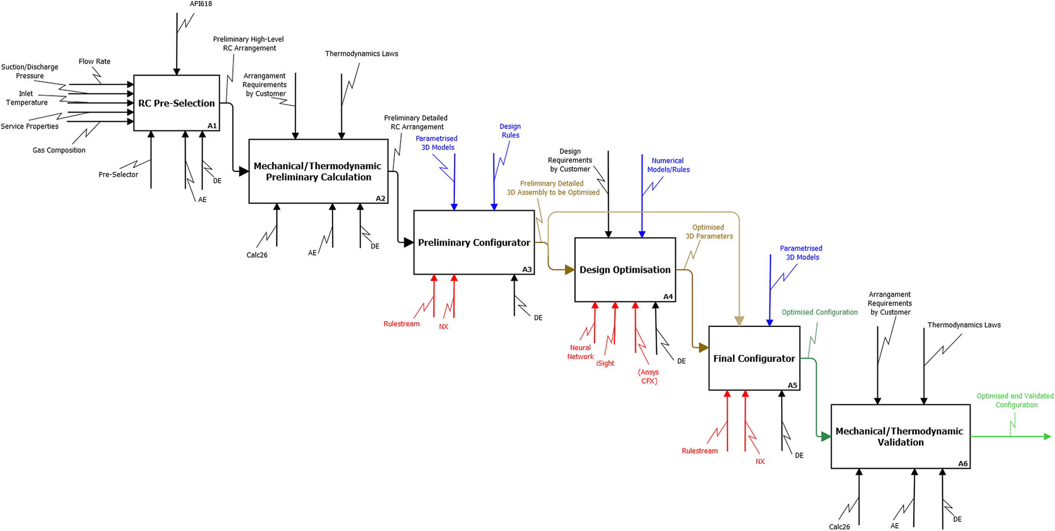
Figure 4. Level 1-IDEF0 Representation of the new RC cylinder design development process.
Figure 5 shows how the different tools are combined together. As outlined before, the process begins with a preliminary configuration tool that defines the initial design parameters. This tool ensures that the base design characteristics are set and ready for further refinement. After the initial configuration, Rulestream is used to create a preliminary 3D model based on the initial design parameters. This stage helps visualize the design early in the process and check for basic compliance with design rules. The Isight tool is used to orchestrate the ANNs during the optimization process. Here, the preliminary set of parameters is refined, resulting in an optimal set of parameters. Isight automates the optimization, adjusting the design based on the target parameters in terms of flow coefficient and clearance volumes. With the optimal set of parameters identified, Rulestream is used once again to generate the final, optimized 3D configuration. This ensures that the design follows all the optimization steps and is ready for final validation.
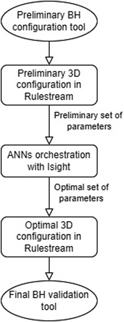
Figure 5. Flowchart showing how the different tools are combined.
The following subsections provide further details about the process and the diverse components of the proposed DA workflow.
Critical parameters for RC cylinder design
One of the most critical parts in the design of RCs and one of the main problems in their design is related to the pressure losses that are generated as the gas flows through the passages of the gas ducts, particularly in the section of the valve pocket, including valves and gas ducts between them and the compression chamber within the cylinders. Optimizing the shape of the gas ducts of a RC’s cylinder can provide several benefits for a company in the market, such as:
-
• Improved efficiency: optimizing the shape of the gas ducts can help reduce energy losses due to turbulence, improving the compressor’s overall efficiency.
-
• Enhanced performance: by optimizing the gas ducts, the compressor can achieve higher flow rates and pressures, which can be beneficial in applications where high levels of compressed gas are required.
-
• Increased reliability: optimizing the shape of the gas ducts can help reduce the likelihood of mechanical failure due to stress, fatigue, or other factors.
Differentiation: by optimizing the shape of the gas ducts, a company can differentiate its products from those of its competitors. In summary, optimizing the shape of the gas ducts of a RC’s cylinders brings several advantages mainly related to efficiency and performance. Indeed, the waste of energy is relevant in a geometry as complex as that of a valve pocket. Therefore, its evaluation becomes a critical aspect for the analysis of the cylinder performance mainly for two reasons:
-
• The pressure drop observed in the valve pocket is an index of the valve’s effectiveness, which is crucial for the work needed to compress the gas.
-
• The relationship between the pressure drop and the mass flow rate must be known during the entire cylinder design process since it is the base of the mathematical model for calculating the p-V cycle characteristic of the compressor.
Additionally, clearance volumes, also known as dead volumes, significantly impact the volumetric efficiency and overall performance of a machine. As the piston reaches the top dead center during the discharge phase, a portion of the gas volume remains uncompressed. The negative impact of clearance volumes on the suction capacity increases with both the size of the clearance volume and the compression ratio.
DA master model
This research focuses on the analysis of a vast database developed by BH, which examines the BH’s complete fleet of RC cylinder families, consisting of over 365 unique cylinders. For each RC cylinder family included in the database, we built a master model of the cylinder assembly suitable to communicate with the other steps of the process. This model considers the critical parameters outlined in Section “Critical parameters for RC cylinder design” and is built to embed the quantitative and qualitative parameters describing the gas flow path that are detailed in Section “Dataset development from the BH archive”. The 3D model is developed through the CAD software Siemens NX. It is a knowledge-based and fully parametric model of an RC cylinder assembly of components embedding all the parameters necessary for the design optimization to goal the target parameters of the study. As this study focuses on the gas pressure losses along the cylinder valve pocket flow path, a finite number of parameters that define the layout of the cylinder geometry in this area, the valve properties, and the cylinder head topology are considered in the master model. These parameters are implemented in a Rulestream model (an example of a master model of a cylinder family made of nodular cast iron is shown in Figure 6), which includes the rules related to the design of an API 618 BH RC cylinder to communicate on different sides of the design process chain with the CAD, PLM software and the optimization tool. This can manage consistent changes in configuration by monitoring and maintaining the constraints of a robust design to overcome the limitations related to the exploration of solutions that are not part of automatically generated design configurations.
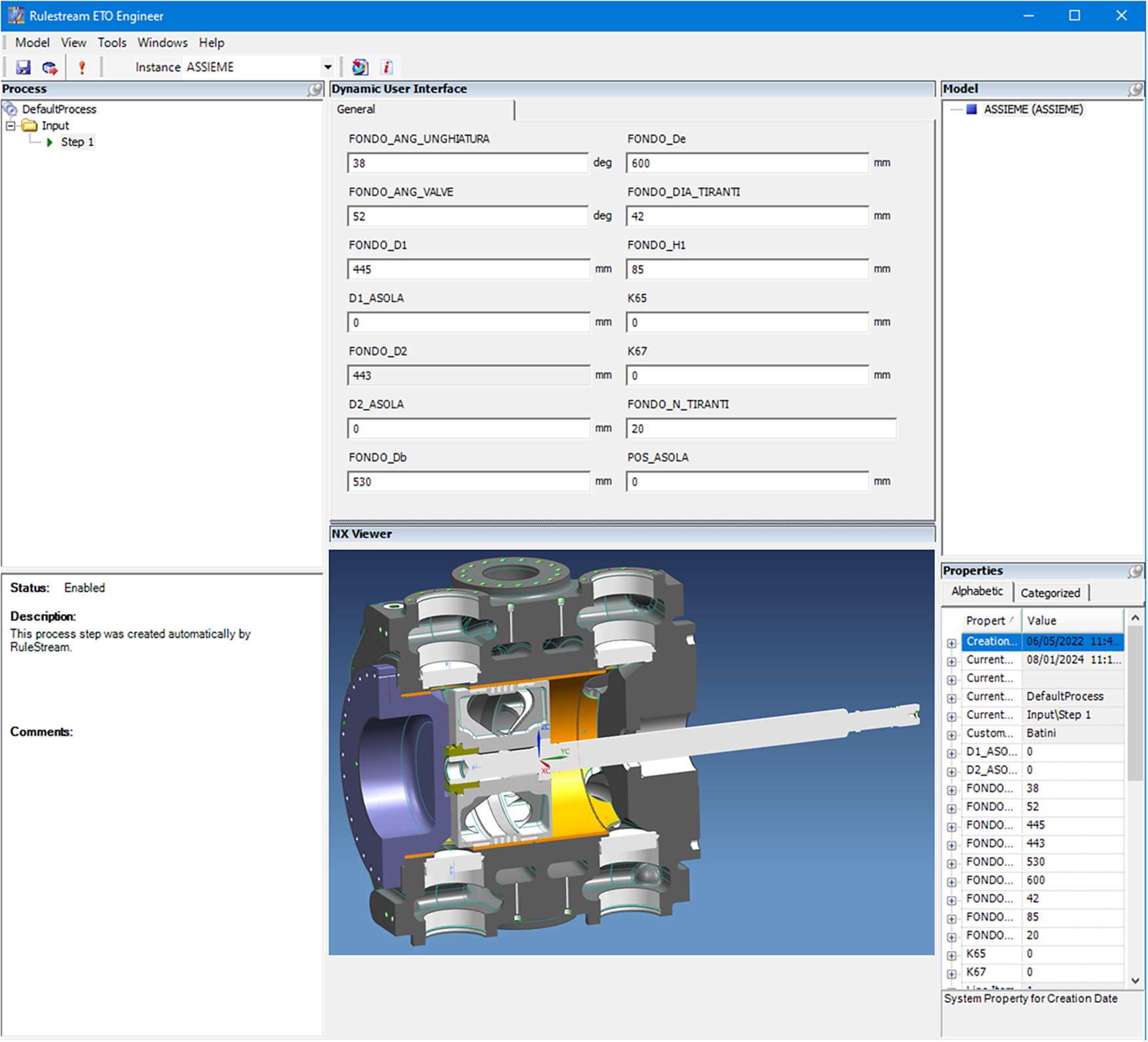
Figure 6. Rulestream model for a nodular cast iron 12 valves-cylinder family.
Dataset development from the BH archive
The common practice at BH is to determine the total losses of a machine through CFD analyses. The total losses are summarized in the global flow coefficient $ {K}_{\mathrm{s}} $
and the clearance volume value
$ {K}_{\mathrm{s}} $
and the clearance volume value $ \varepsilon $
. The flow coefficient
$ \varepsilon $
. The flow coefficient $ {K}_{\mathrm{s}}=\frac{{\dot{m}}_{\mathrm{real}}}{{\dot{m}}_{\mathrm{id}}} $
represents the ratio between the actual and ideal gas flow rates through the RC valves, which is necessary to obtain the real mass flow rate through the same valve once the pressure drop has been established. The clearance volume
$ {K}_{\mathrm{s}}=\frac{{\dot{m}}_{\mathrm{real}}}{{\dot{m}}_{\mathrm{id}}} $
represents the ratio between the actual and ideal gas flow rates through the RC valves, which is necessary to obtain the real mass flow rate through the same valve once the pressure drop has been established. The clearance volume $ \varepsilon =\frac{{\mathrm{V}}_{\mathrm{TDC}}}{V_{\mathrm{C}}} $
represents the percentage of the volume remaining among the piston, cylinder head, and valves of an RC cylinder when the piston reaches the top dead centre relative to the cylinder capacity. DEs can monitor these two parameters to assess the performance of the RC cylinder and calculate the absorbed power declared to the customer, which is a function of both
$ \varepsilon =\frac{{\mathrm{V}}_{\mathrm{TDC}}}{V_{\mathrm{C}}} $
represents the percentage of the volume remaining among the piston, cylinder head, and valves of an RC cylinder when the piston reaches the top dead centre relative to the cylinder capacity. DEs can monitor these two parameters to assess the performance of the RC cylinder and calculate the absorbed power declared to the customer, which is a function of both $ {K}_{\mathrm{s}} $
and
$ {K}_{\mathrm{s}} $
and $ \varepsilon $
:
$ \varepsilon $
:
 $$ {\mathrm{P}}_{\mathrm{ABS}}=f\left({K}_{\mathrm{s}},\varepsilon \right) $$
To obtain these values, extensive simulations are needed, with a single cylinder taking approximately 10 hours of computation on a six core-processor able to parallelize the run. In the past, most studies focused solely on analyzing valve pressure losses. However, with changes to gas duct layouts over time, the losses of all the other components of the machine have become crucial. CFD simulations have shown potential for studying the entire reciprocating compressor but are limited by high computational costs. Unfortunately, such analyses’ timing often conflicts with BH ETO process schedules, making it challenging to allocate sufficient resources and computational time. Therefore, there is a need to explore innovative methods to quickly design RC cylinders that can meet customer demands.
The database used for this work and available through tools owned by BH includes for every cylinder:
-
• Cylinder name, with a code that identifies the cylinder;
-
• Cylinder bore;
-
• Cylinder valves size and number;
-
• Six geometric parameters describing the gas flow path layout. Indeed, several factors influence the performance of the cylinder concerning $ {K}_{\mathrm{s}} $
and
$ \varepsilon $
. These include distances, angles, and cylinders component dimensions;
$ {K}_{\mathrm{s}} $
and
$ \varepsilon $
. These include distances, angles, and cylinders component dimensions; -
•
$ {K}_{\mathrm{s}} $
for the two phases (i.e., suction and discharge), both at the head and crank-end of the cylinder; -
•
$ \varepsilon $
both for the head and crank-end of the cylinder and the medium value between the two.


To simplify the analysis, the database was rearranged as follows: $ {K}_{\mathrm{s}} $
was evaluated for the suction phase of the head-end side of the cylinder, and the medium value between the head and crank-end side of the cylinder was considered for
$ {K}_{\mathrm{s}} $
was evaluated for the suction phase of the head-end side of the cylinder, and the medium value between the head and crank-end side of the cylinder was considered for $ \varepsilon $
. This approach analyses only the suction phase of the head-end side of the cylinder, resulting in eight independent parameters and two dependent variables (
$ \varepsilon $
. This approach analyses only the suction phase of the head-end side of the cylinder, resulting in eight independent parameters and two dependent variables ( $ {K}_{\mathrm{s}} $
and
$ {K}_{\mathrm{s}} $
and $ \varepsilon $
) for each of the 365 different cylinders in the original database. While some variables, such as the number and size of valves, are discrete with standard values, other variables are represented as discrete geometrical values that could theoretically be continuously altered by an ANN. Based on the analysis of this heterogeneous database, the physics of the problem, and the literature reviewed in Section “Related work and state-of-the-art”, a metamodel is developed to represent the independent variables affecting the two dependent variables. This metamodel is presented in the following subsections.
$ \varepsilon $
) for each of the 365 different cylinders in the original database. While some variables, such as the number and size of valves, are discrete with standard values, other variables are represented as discrete geometrical values that could theoretically be continuously altered by an ANN. Based on the analysis of this heterogeneous database, the physics of the problem, and the literature reviewed in Section “Related work and state-of-the-art”, a metamodel is developed to represent the independent variables affecting the two dependent variables. This metamodel is presented in the following subsections.
To understand how the different variables are distributed in the design space of the dataset and how they are correlated to each other, a correlation matrix plot is presented in Figure 7. Variables have been clustered according to their nature within the dataset. Geometrical and quantitative parameters describing the gas duct are highlighted in blue, while the relationship between the two variables representing the performance of the cylinder and their distributions are highlighted in green. The correlations between each parameter of the first type and each of the parameters of the second type are highlighted in orange. In this chart, each off-diagonal subplot contains a scatterplot of pairs of variables with least-squares reference lines with slopes equal to the displayed correlation coefficients, while each diagonal subplot contains the distribution of the variable as a histogram. Additionally, each cell of the correlation matrix shows the correlation coefficient, which measures the strength and direction of the linear relationship between two variables. It quantifies how closely the variables are related to each other. The correlation coefficient typically ranges from −1 to +1. Values close to +1 or − 1 suggest a strong correlation, while values closer to 0 indicate a weaker correlation.
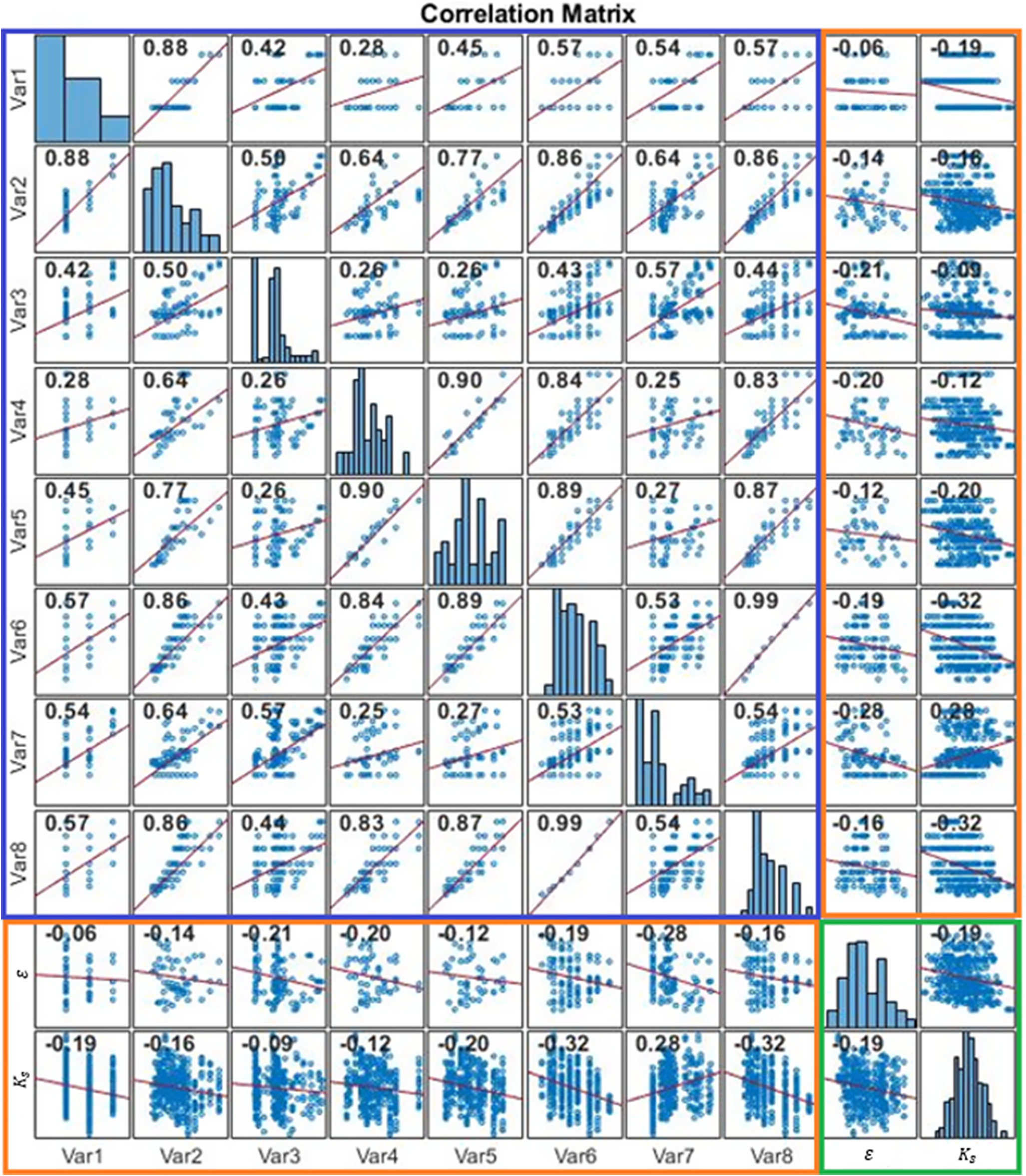
Figure 7. Correlation matrix between all pairs of variables.
For confidentiality reasons, the geometrical parameters of the various cylinders present in the database are herein masked and shown as Var1 to Var8. In Figure 6, the last two variables are related to the values of clearance volumes $ \varepsilon $
and flow coefficient
$ \varepsilon $
and flow coefficient $ {K}_s $
, respectively. The correlation matrix plot shows that, apart from the discrete variables (i.e., Var1, Var6, and Var8), most of the variables are sparsely distributed throughout the design space. It also demonstrates that some of them are moderately correlated (i.e., Var2 and Var3), others are strongly linearly correlated (i.e., Var6 and Var8), while other variables appear weakly correlated with each other (i.e., Var1 and
$ {K}_s $
, respectively. The correlation matrix plot shows that, apart from the discrete variables (i.e., Var1, Var6, and Var8), most of the variables are sparsely distributed throughout the design space. It also demonstrates that some of them are moderately correlated (i.e., Var2 and Var3), others are strongly linearly correlated (i.e., Var6 and Var8), while other variables appear weakly correlated with each other (i.e., Var1 and $ \varepsilon $
).
$ \varepsilon $
).
The dataset analysis reinforces the assumption to apply ANNs for the purpose of this research, as they can be particularly effective for handling heterogeneous and sparse data and for capturing complex, non-linear relationships when finding correlations between the different variables is difficult.
ANNs: training and performance estimation
The possibility that the application of ANNs can provide an optimal design solution for an RC cylinder outside the boundaries of the design space represented by its training dataset in place of more computationally expensive optimization methods is herein analyzed. With this purpose, the database has been prepared and imported into MATLAB, which has been chosen together with the BH IT department as the most suitable software for this analysis due to its extensive toolset, ease of use, and integration capabilities with the other BH tools with already available licenses. Within this development environment, a feed-forward algorithm has been implemented.
Ensemble modeling is a powerful technique that can help improve the performance and generalization of a machine learning model (Ganaie et al., Reference Ganaie, Hu, Malik, Tanveer and Suganthan2022). By training multiple neural networks and averaging their results, we can reduce overfitting, improve accuracy, and obtain more reliable uncertainty estimates (Yu et al., Reference Yu, Wang and Lai2008). This technique is beneficial when dealing with large and complex datasets, where a single neural network may struggle to learn all the underlying patterns in the data. Ensembling multiple networks can help capture a more diverse set of representations of the data and produce a more robust and generalized model (Kotu and Deshpande, Reference Kotu and Deshpande2014).
With this purpose, 30 feed-forward ANNs with a single hidden layer of size 20 were created and trained to correlate 8 input parameters describing the type and geometry of the cylinder to the 2 performance parameters (i.e., $ \varepsilon $
and
$ \varepsilon $
and $ {K}_{\mathrm{s}} $
) as an output. The number related to the hidden layer size and number of ANNs for the ensemble modeling are the results of a trade-off obtained through a sensitivity analysis: the time needed for training and executing one calculation together with the output quality have been evaluated for various configurations of ANNs with different hidden layer sizes, ranging from 10 to 40 being equal to the number of ANNs (10), and for ensemble modeling, with a number of ANNs varying from 10 to 100 being equal to the hidden layer size (10). The quality of the output of ANNs (cfr. Tables 3 and 4) was assessed through the mean absolute percentage error (MAPE), defined as:
$ {K}_{\mathrm{s}} $
) as an output. The number related to the hidden layer size and number of ANNs for the ensemble modeling are the results of a trade-off obtained through a sensitivity analysis: the time needed for training and executing one calculation together with the output quality have been evaluated for various configurations of ANNs with different hidden layer sizes, ranging from 10 to 40 being equal to the number of ANNs (10), and for ensemble modeling, with a number of ANNs varying from 10 to 100 being equal to the hidden layer size (10). The quality of the output of ANNs (cfr. Tables 3 and 4) was assessed through the mean absolute percentage error (MAPE), defined as:
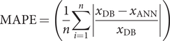 $$ \mathrm{MAPE}=\left(\frac{1}{n}\sum_{i=1}^n\left|\frac{x_{\mathrm{DB}}-{x}_{\mathrm{ANN}}}{x_{\mathrm{DB}}}\right|\right) $$
where $ {x}_{\mathrm{DB}} $
is the generic variable present in the database,
$ {x}_{\mathrm{DB}} $
is the generic variable present in the database, $ {x}_{\mathrm{ANN}} $
is the same variable calculated by the ANN, and
$ {x}_{\mathrm{ANN}} $
is the same variable calculated by the ANN, and $ n $
is the number of samples present in the database.
$ n $
is the number of samples present in the database.
Table 3. MAPEs obtained through different hidden layer sizes
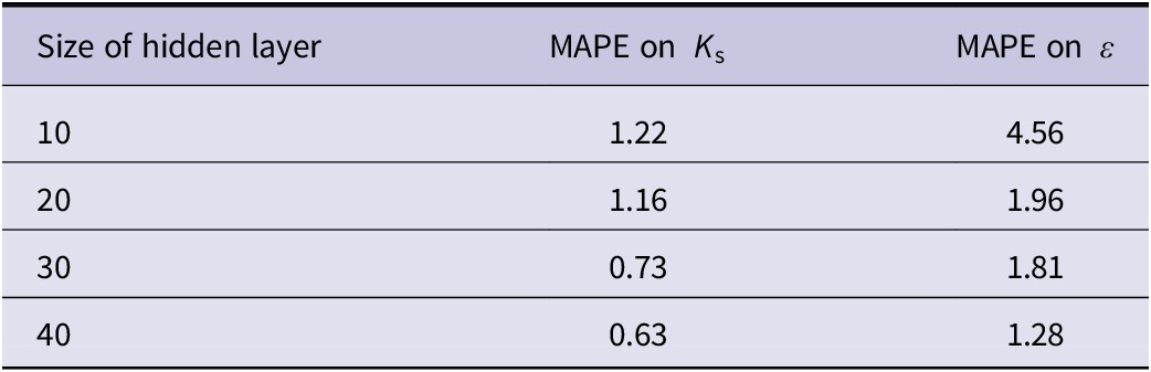
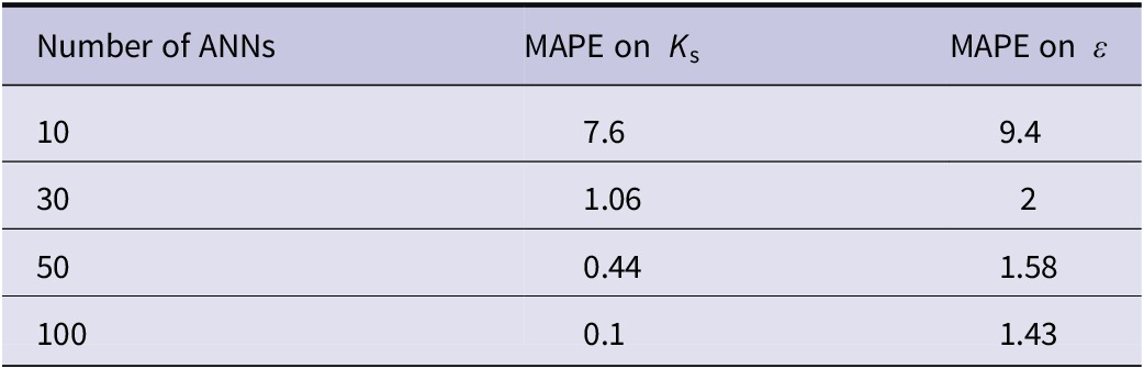
Table 4. MAPEs obtained through different numbers of ensembled ANNs
The analysis concerning the training time related to the size of the hidden layer is reported in Figure 8, while the analysis regarding the number of ANNs is summarized in Figure 9.
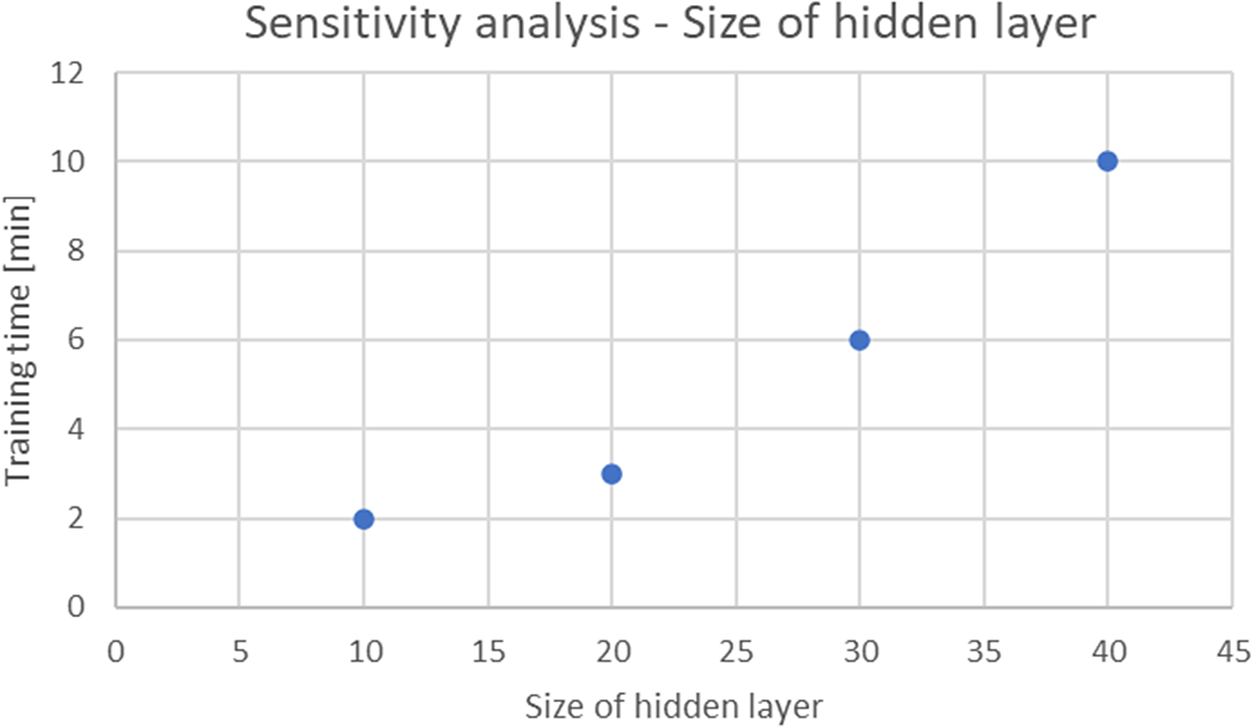
Figure 8. The size of the hidden layer ranged from 10 to 40.
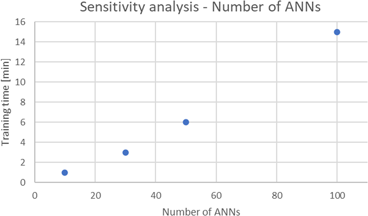
Figure 9. The number of ANNs of the ensembled model ranged from 10 to 100.
The ANNs used in this study were trained using MATLAB’s trainnet function, which automatically splits the dataset into training, validation, and test sets to ensure robust performance evaluation through a k-fold cross-validation approach. The training set is utilized to optimize the network’s weights, the validation set monitors the model to prevent overfitting, and the test set is used for final performance assessment on unseen data. This method ensures that the ANN is trained and evaluated on multiple data partitions, providing a comprehensive assessment of its performance across different data splits. Additionally, an ensemble of ANN models was created, where the final prediction was obtained by averaging the outputs of multiple models. This ensemble approach has been checked by the authors by comparing the variability of errors against the number of ANNs as shown in Table 4, confirming the model’s robustness.
To ensure that the performance of the RC machine meets the customer’s expectations, it is crucial to evaluate the impact of errors in the $ {K}_{\mathrm{s}} $
and
$ {K}_{\mathrm{s}} $
and $ \varepsilon $
values on the absorbed power. The ANNs’ quality has been verified by comparing the outputs generated by the ANNs to the same dataset sample. The accuracy of the prediction method was assessed using the MAPE for both the
$ \varepsilon $
values on the absorbed power. The ANNs’ quality has been verified by comparing the outputs generated by the ANNs to the same dataset sample. The accuracy of the prediction method was assessed using the MAPE for both the $ {K}_{\mathrm{s}} $
and
$ {K}_{\mathrm{s}} $
and $ \varepsilon $
variables.
$ \varepsilon $
variables.
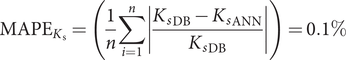 $$ {\mathrm{MAPE}}_{K_{\mathrm{s}}}=\left(\frac{1}{n}\sum_{i=1}^n\left|\frac{{K_s}_{\mathrm{DB}}-{K_s}_{\mathrm{ANN}}}{{K_s}_{\mathrm{DB}}}\right|\right)=0.1\% $$
 $$ {\mathrm{MAPE}}_{\varepsilon }=\left(\frac{1}{n}\sum_{i=1}^n\left|\frac{\varepsilon_{\mathrm{DB}}-{\varepsilon}_{\mathrm{ANN}}}{\varepsilon_{\mathrm{DB}}}\right|\right)=1.43\% $$
where:
-
•
$ {K_s}_{\mathrm{DB}} $
is the value of the flow coefficient present in the database; -
•
$ {K_s}_{\mathrm{ANN}} $
is the value of the flow coefficient calculated with the ANNs; -
•
$ {\varepsilon}_{\mathrm{DB}} $
is the value of the mean clearance volume present in the database; -
•
$ {\varepsilon}_{\mathrm{ANN}} $
is the value of the mean clearance volume calculated with the ANNs; -
•
$ n $
is the number of cylinders present in the database.


A MAPE on $ {K}_{\mathrm{s}} $
of 0.1% and on
$ {K}_{\mathrm{s}} $
of 0.1% and on $ \varepsilon $
of 1.43% leads to an error of 0.1% on the declared absorbed power, which has been considered acceptable with respect to API 618 standard, as customers typically accept a larger tolerance on that value (3%). The difference between the two MAPEs can be addressed through the simplifications of the dataset, with respect to the averaged value of each clearance volume
$ \varepsilon $
of 1.43% leads to an error of 0.1% on the declared absorbed power, which has been considered acceptable with respect to API 618 standard, as customers typically accept a larger tolerance on that value (3%). The difference between the two MAPEs can be addressed through the simplifications of the dataset, with respect to the averaged value of each clearance volume $ \varepsilon $
, summarised in Section “Dataset development from the BH archive”, while each value of the flow coefficient
$ \varepsilon $
, summarised in Section “Dataset development from the BH archive”, while each value of the flow coefficient $ {K}_{\mathrm{s}} $
present in the database has been considered as-is.
$ {K}_{\mathrm{s}} $
present in the database has been considered as-is.
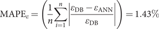
A cross-check of the quality of the network has been made through the error histogram with respect to the clearance volume values (as it seems to be the parameter with the highest MAPE), which shows the distribution of errors between predicted and target values after training a feed-forward neural network. The histogram (cf. Figure 10) indicates that over 85% of the predictions had errors within a range of −0.23 to 0.15, with a relative error of 1.32% on the average clearance volume. These results demonstrate the reliability of the ANN for predicting the desired outputs in the environment.
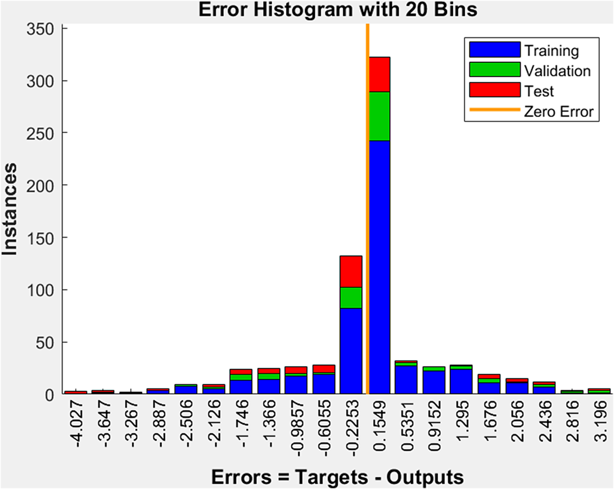
Figure 10. Error histogram for clearance volume calculation.
ANN integration in the DA process
This subsection depicts the methodology aiming to integrate the ANNs in the overall design process by orchestrating the different parameters playing a crucial role in targeting customer requirements. This is described through an IDEF0 diagram (cf. Figure 11) with respect to process A4, as shown in Figure 4. The preliminary parameters of the baseline configuration are exported from Rulestream, which is used as a knowledge-based 3D configurator. The trained and validated ANNs are integrated and orchestrated into a DA tool able to deliver the optimal solution once the computational goals have been set. As outlined before, Isight is an orchestrator used to combine multiple models and multi-disciplinary applications into a simulation process flow, automate execution across distributed computing resources, explore the resulting design space, and identify optimal design parameters responding to the required constraints. The MATLAB routine of the feed-forward ANNs algorithm is managed by the orchestrator to goal the target values set as a computational input. The output of this run is the set of parameters of the optimized RC cylinder assembly, which are exported back into the configurator, that embeds the parametric 3D models to deliver the optimal configuration required by the customer. By exploiting the functionality of this integration, this method is able to communicate on both sides of the design process, from the preliminary layout to the optimal design configuration of the cylinder able to meet customer requirements.
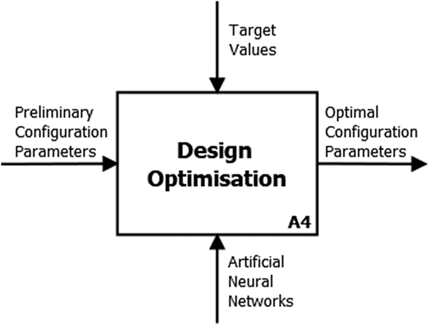
Figure 11. ANNs orchestrated in the DA process.
Computational pipeline applications
To validate the proposed workflow and answer the RQs, three different case studies of BH RC cylinders have been carried out. They are representative of three different real job situations described in the following subsections. With reference to the abovementioned RQs, the purpose is to prove that an advanced and innovative DA process with the integration orchestrated ANNs can be a valid alternative to more expensive optimization methods based on CFD, which has been considered the benchmark of the analysis.
Cylinders description
-
a. The first case (cf. Figure 12) is a non-routine design modification of the geometrical parameters present in the DA master model (i.e., the ones that describe the gas flow path between the valves and the compression chamber) of a cylinder, which is part of the dataset on which the ANNs have been trained. This cylinder is a standard forged steel cylinder with a total of 4 valves. The customer required a target value of absorbed power (which means
$ {K}_s $
and
$ \varepsilon $
). It is necessary to modify the geometrical parameters of the gas path to meet customer requirements. This is a typical ETO job that is often performed by BH.


-
b. The second case (cf. Figure 13) is part of a new product development program planned after the customer’s request to increase the whole machine’s power density. The new cylinder is a member of a new family that is scaled up from an existing cast steel cylinder, with a total of 8 valves, which the ANNs have been trained on. Physically, this case study involves the development of a new cylinder with an overall shape similar to others already present in BH’s portfolio but with a different combination of parameters (i.e., geometrical parameters, such as the compression chamber bore, and architectural parameters, such as the total number of valves), placing this cylinder outside the design space proper of the dataset on which the related ANNs have been trained. The analysis aims to reach a goal value of performance similar to that of the existing family, which results in target values of
$ {K}_s $
and
$ \varepsilon $
. Targeting this performance, together with increasing the capacity of the cylinder, allows BH to meet the job’s requirements.


-
c. The third case study (cf. Figure 14) is part of the same project as the second one. Unlike the case study b, the baseline is an entirely new cylinder, especially in terms of the gas flow path. Unlike the other cylinders of the same family obtained by forged steel, this unique cylinder has a total of eight valves, which leads to a particularly innovative shape of the gas ducts. The overall layout of this cylinder places it outside the design space of the cylinder’s families on which the ANNs have been trained. In this case, the study aims to set a target value in terms of
$ {K}_{\mathrm{s}} $
and
$ \varepsilon $
, proper to cylinders with the same number of valves that are obtained by cast steel, which is the benchmark in terms of product competitiveness.


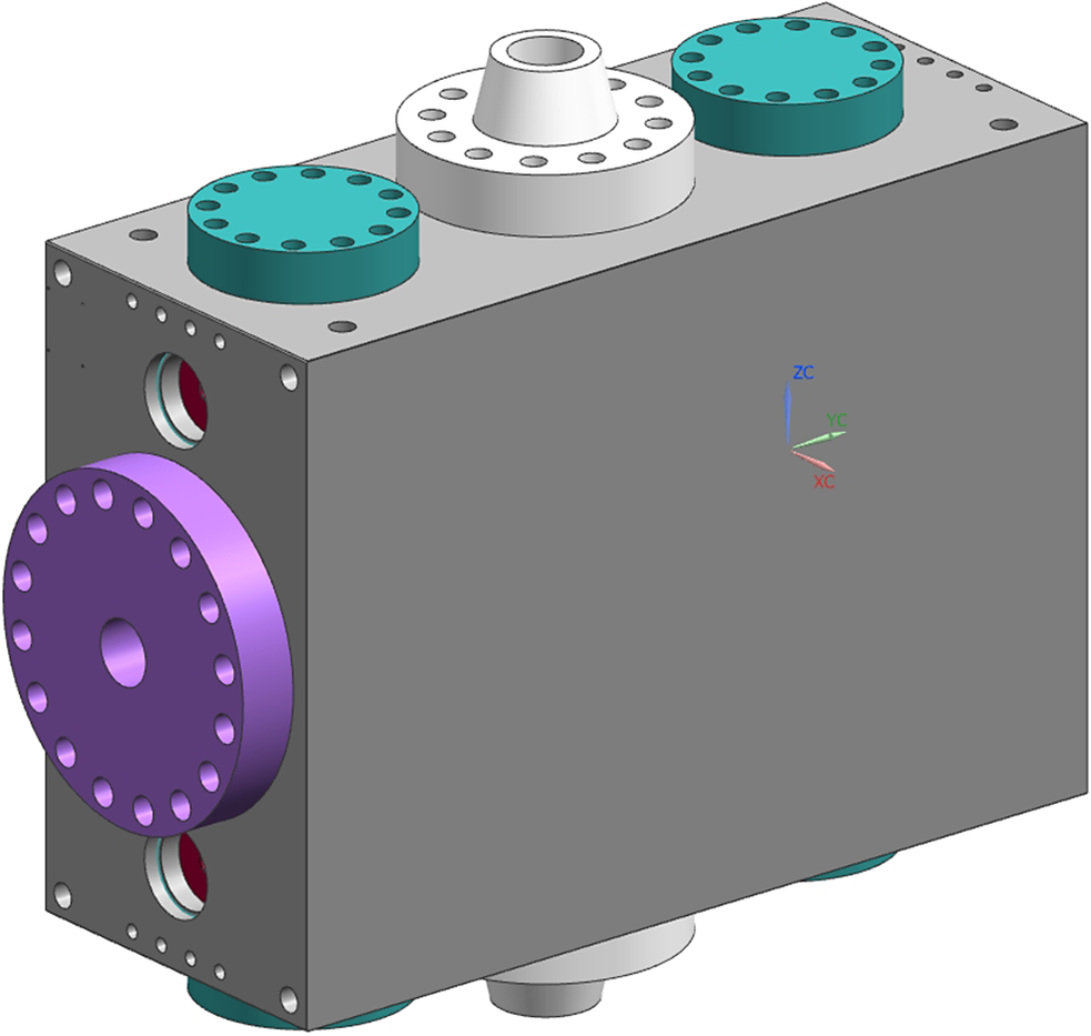
Figure 12. Cylinder of the first case study (a).
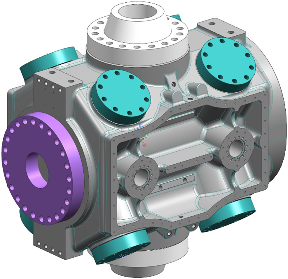
Figure 13. Cylinder of the second case study (b).
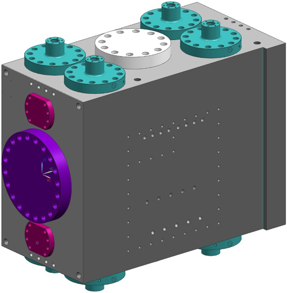
Figure 14. Cylinder of the third case study (c).
Pipeline execution
For each case study, the execution of the computational pipeline of the proposed integrated DA method has been carried out and its results have been compared with a complete CFD analysis performed separately with the cylinder configuration previously obtained through the DA method itself. This comparison is needed to verify the KPIs of the study.
Integrated method
The computational pipeline of each of the presented case studies can be summarized as follows. With the inputs coming from the product specifications required by the customer, the preliminary calculation outlined a preliminary configuration of the cylinder, which is configured by Rulestream thanks to the specific 3D master model previously developed through the main properties of the cylinder assembly. The parameters of this configuration have been exported to Isight, where these preliminary parameters have been set according to the corresponding master model parameters. The goal parameters of $ {K}_s $
and
$ {K}_s $
and $ \varepsilon $
of this case study has been set in the specific tab of the software. The other 8 parameters have been modified by the orchestrator to reach the final configuration that is able to respond to the requirements. The final parameters have been implemented in the 3D configuration of the cylinder.
$ \varepsilon $
of this case study has been set in the specific tab of the software. The other 8 parameters have been modified by the orchestrator to reach the final configuration that is able to respond to the requirements. The final parameters have been implemented in the 3D configuration of the cylinder.
Despite this being a prototype version of the integrated DA method, if each step of the process does not involve manual data elaboration or human decision, the process can be fully automated.
CFD
With the obtained design configuration, a complete CFD analysis was carried out in stationary conditions, and its results were compared with those obtained through the integrated DA model to verify the KPIs of the study. The steps necessary to obtain the benchmark are detailed in the following:
-
1) The 3D model has been defeatured, and the volume of gas contained within the cylinder walls (i.e., gas solid) necessary for the setup of the CFD analysis has been obtained by Boolean subtraction. Clearance volume values are computed through Siemens NX CAD evaluation (cf. Figure 15);
-
2) The volume of gas has been imported into Ansys CFX software (https://www.ansys.com/it-it/products/fluids/ansys-cfx, last access on 21/11/2023);
-
3) The inlet gas pressure was set at the inlet surface, a wall condition was imposed as a constraint to simulate the presence of the metal, and the average piston velocity was at the outlet surface to complete the boundary conditions of the model (cf. Figure 16). The valves are simulated as a porous septum;
-
4) After the CFD run, the results have been exported in a specific MS Excel macro that correlates the different variables through the flow path (i.e., the pressure losses) to obtain the values of the flow coefficient
$ {K}_s $
.

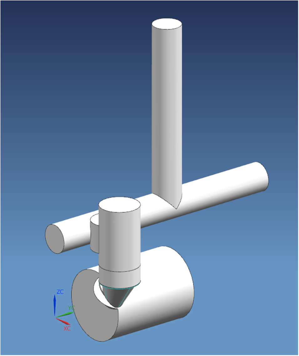
Figure 15. Volume of gas for CFD analysis and clearance volume evaluation.
Figure 16. Ansys CFX model to simulate the fluid-dynamic behavior of the cylinder.
Results and discussion
ANN results summary
The results of the ANN for the different case studies are summarized in Figure 17, containing the configuration of the three cylinders according to each variable represented in the related boxplot with respect to the statistics of the variables of the dataset themselves (i.e., distributions, medians, quartiles, and range of data). Using boxplots to compare the results of ANN predictions with original design parameters is a powerful visual and analytical tool. It aids in assessing data distribution, detecting outliers, and above all, evaluating the consistency of the neural network’s predictions. If the boxplots of different case studies exhibit consistent patterns or variations, it provides insights into the reliability and robustness of the optimization process.
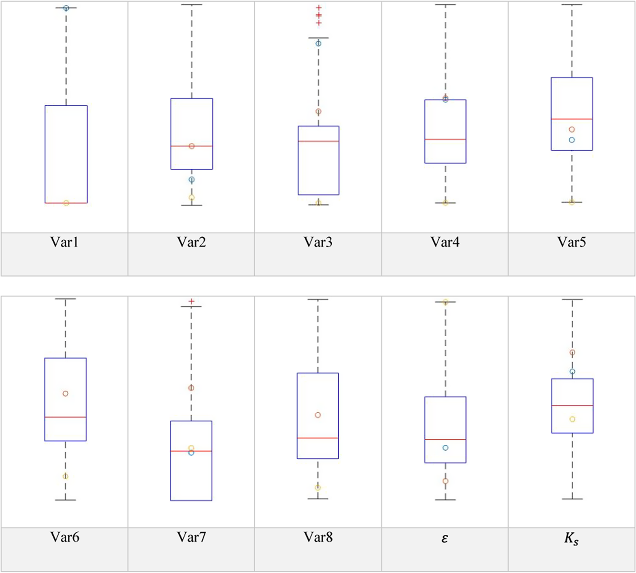
Figure 17. Boxplots summarizing ANN results.
Case study a is shown in yellow, case study b is shown in red, and case study c is represented in blue. There are overlaps of values of Var1 for cases a and b, Var6 for cases b and c, and Var8 for cases b and c (which are the discrete variables of the dataset, representing quantitative parameters).
In general, it seems that no outliers have been generated by the metamodel, with values corresponding to the different configurations of the cylinders falling in the distributions of the dataset variables. Furthermore, it emerges that the results obtained through the ANNs are independent of the geometry of the DA master model and the cylinder itself.
More specifically, and for case studies b and c in particular, it is demonstrated that even starting from a baseline configuration of a cylinder that is not included in the original dataset, the ANN delivers results regarding the single variables that are consistent with the original one in terms of distribution within the design space, although the overall topology of the flow path may vary significantly.
Comparison with CFD simulations
Having good predictability of machine performance is crucial for several reasons: it supports efficient operations, cost-effectiveness, quality assurance, customer satisfaction, and competitive advantage in industrial applications.
At the same time, assessing the design lead time of the proposed methodology applied to RC cylinders is crucial to evaluate the industrial impact of the integrated DA method, too. Design process lead time refers to the duration it takes for a design to move from the initial concept stage to completion. It’s important in industrial applications because it directly impacts time-to-market, engineering cost, and overall efficiency of the process.
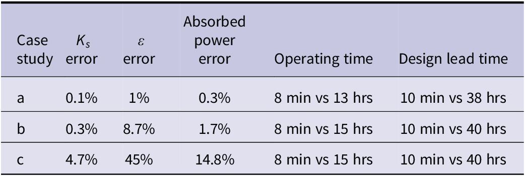
The results, summarized in Table 5, are as follows:
-
a. For the first case study, the error between
$ {K}_{{\mathrm{s}}_{\mathrm{ANN}}} $
obtained with the metamodel and
$ {K}_{{\mathrm{s}}_{\mathrm{CFD}}} $
obtained with the CFD model is 0.1%, while the error between
$ {\varepsilon}_{\mathrm{ANN}} $
obtained with the metamodel and
$ {\varepsilon}_{\mathrm{CFD}} $
obtained with the CFD model is 1%, which results in an error in the estimated absorbed power of 0.3%. The design lead time to deliver the optimal configuration with the integrated method is 10 minutes vs approximately 38 hours needed to set up (8 hours), run the CFD model (25 hours with a 6 core-processor workstation able to parallelize the calculation), and export the results (5 hours). -
b. For the second case study, the error between
$ {K}_{{\mathrm{s}}_{\mathrm{ANN}}} $
obtained with the metamodel and
$ {K}_{{\mathrm{s}}_{\mathrm{CFD}}} $
obtained with the CFD model is 0.3%, while the error between
$ {\varepsilon}_{\mathrm{ANN}} $
obtained with the metamodel and
$ {\varepsilon}_{\mathrm{CFD}} $
obtained with the CFD model is 8.7%, which results in an error in the estimated absorbed power of 1.7%. The design lead time to deliver the optimal configuration with ANNs is 10 minutes vs approximately 40 hours needed to set up (10 hours), run the CFD model (25 hours with the same workstation), and export the results (5 hours). -
c. For the third case study, the error between
$ {K}_{{\mathrm{s}}_{\mathrm{ANN}}} $
obtained with the metamodel and
$ {K}_{{\mathrm{s}}_{\mathrm{CFD}}} $
obtained with the CFD model is 4.7%, while the error between
$ {\varepsilon}_{\mathrm{ANN}} $
obtained with the metamodel and
$ {\varepsilon}_{\mathrm{CFD}} $
obtained with the CFD model is 45%, which results in an error in the estimated absorbed power of 14.8%. The design lead time to deliver the optimal configuration with ANNs is 10 minutes vs approximately 40 hours needed to set up (10 hours), run the CFD model (25 hours with the same workstation), and export the results (5 hours).


Table 5. Results of the computational pipeline applications
Discussion
The methodology described in the previous sections outlines an approach able to deliver the expected results in terms of the predictive capability of an advanced DA process for RCs cylinders design and computational time to deliver the desired solution (cf. RQ2).
-
a. The first case study (i.e., modification of some geometrical parameters of an existing standard cylinder) sees negligible errors between results in terms of cylinder performance (i.e., absorbed power) of the metamodel and the CFD with a reduction of time needed to deliver the final solution from approximately 38 hours to 10 minutes, which is a relevant added value that can be addressed to RQ2.
-
b. With reference to RQ2, the second case study (i.e., new cylinder, scale-up of an existing standard cylinder) shows that the error between results in terms of cylinder performance (i.e., absorbed power) of the metamodel and the CFD (1.7%) is lower than the tolerance accepted by the customer and API 618 standard (3%), with a reduction of time needed to deliver the solution from approximately 40 hours to 10 minutes.
-
c. In the third case study (i.e., disruptive concept from the point of view of the cylinder type), the error between results in terms of cylinder performance (i.e., absorbed power) of the metamodel and the CFD is 14.8%, with a reduction of time needed to deliver the solution from approximately 40 hours to 10 minutes. Possible reasons for the discrepancy in power absorption estimation can be addressed by the fact that the type of this new cylinder embeds a new and innovative topology of the gas ducts with respect to the ones belonging to the families on which the ANNs have been trained. Furthermore, the larger error in the predicted clearance volume could also be due to the mean value between the head and crank-end sides of the cylinder, which has been chosen to simplify the study and may amplify the error in the suction phase of the head-end side.
With respect to RQ2, the findings show that the metamodel generated using DA strategies can accurately predict the performance of a modified cylinder design with negligible errors compared to CFD. This demonstrates that DA strategies, through an integrated approach, can be used to explore alternative design configurations not included in the initial design space while reducing the time needed to obtain the final solution in terms of the design layout of the components assembly layout. In this regard, it is useful to remember that the proposed integrated method only concerns the configuration of the machine, the process upstream and downstream of the layout optimization being out of the scope of the research project. The three case studies illustrate the benefits of using metamodels (i.e., machine learning models trained on data from simulations) to accelerate the design process and reduce the computational time needed for simulations. This approach overcomes several main limitations of traditional DA methods when ANNs are used (Woldemariam and Lemu, Reference Woldemariam and Lemu2019) and helps fill the research gaps that RQ2 has been based on, such as:
-
• High computational cost: from the literature review, it emerges that traditional methods such as CFD typically require extensive simulations, which can take a long time to run on high-performance computing systems (Nakano and Kinjo, Reference Nakano and Kinjo2008). The metamodel implemented in this work, on the other hand, can deliver accurate results very rapidly, as the results are delivered in a few minutes, even with common computational resources. Of course, this can be done if a sufficiently large and representative database can allow ANNs to replace CFD and if the expected configuration variations compared to the initial design space are relatively limited.
-
• Limited exploration of design space: traditional DA methods are often limited by the amount of computational resources available, which can make it difficult to explore the full design space (Entner et al., Reference Entner, Prante, Vosgien, Zavoianu, Saminger-Platz, Schwarz and Fink2019). The integrated method proposed in this work, on the other hand, can quickly evaluate multiple design options, allowing for a more comprehensive exploration of the design space, as in the case of the third case study, where a disruptive gas flow path layout of a new cylinder has been developed.
-
• Lack of flexibility: classical DA methods present in the literature can be inflexible, requiring a fixed set of parameters and assumptions to manage product complexity (Thomassen and Alfnes, Reference Thomassen and Alfnes2017). An integrated approach such as the one presented in this work, on the other hand, can adapt to new data and can be retrained to reflect changes in the design or operating conditions.
However, some limitations remain when integrating metamodels in DA, such as:
-
• Dependence on training data: metamodels rely on training data, and the accuracy of the model depends on the quality and quantity of the data used to train it. If the training data are not representative of the design space, the model may not provide accurate predictions;
-
• Need for validation: although metamodels can provide a rapid means of exploring the design space, it is still important to validate the results using more detailed simulations or experimental data to ensure that the model accurately captures the behaviour of the system.
Conclusions and future perspectives
This paper presents an advanced integrated DA process capable of configuring an optimal design of systems of turbomachinery components. In particular, the final configuration of the target system (i.e. RC cylinder assembly) is developed by seeking goal values of a multi-objective function related to the machine’s performance.
The two RQs introduced in Section “Introduction” have been answered throughout the paper. In summary:
-
1) A dedicated literature research has been carried out to highlight the ANN-based tools and methods that may support DA processes in the ETO turbomachinery industry. Existing ANN-based approaches can develop and process relationships between variables of heterogeneous datasets. They have already been used in turbomachinery to replace classical optimization methods when a quick response is needed. They are potential enablers for DA processes in the ETO turbomachinery industry.
-
2) It has been demonstrated that the proposed methodology works for the design solutions of RC cylinders. It is suitable for design solutions of RCs cylinders, as both the developed master models for DA purposes and the related metamodels can respond with flexibility of design and sufficient performance estimation to different inputs (i.e., with an error < 2% calculated on the absorbed power for case study a and b). With a more general perspective, the benefits of this integrated approach to industrial practice are mainly related to the capability of the presented methodology to deliver a design solution that meets customer requirements with sufficient accuracy in a design time two orders of magnitude lower than traditional methods.
This paper demonstrates the methodology’s viability for the ETO industry in facilitating the DA processes by managing changes in the topology of the cylinders used as a case study. It also shows the ANNs predictive ability for assessing cylinder and machine performance compared to time-consuming CFD models. Despite continuous computational potential improvements, real-time machine evaluations are crucial for ETO purposes. The advanced integrated DA method proves reliable for DEs requiring quick modifications to existing turbomachinery designs. ANNs enable achieving final configurations within minutes without running complete CFD models, making them suitable for ETO activities in customer-driven engineering.
Results show that the metamodel performs well within trained boundaries (case study a) and provides sufficiently accurate predictions beyond those boundaries (case study b). However, in cases requiring creative gas duct redesign (case study c), ANNs may introduce errors exceeding acceptable tolerances, necessitating cross-verification with comprehensive CFD models. In cases similar to this, the integrated method’s validity may be reflected in developing curves and maps correlating model parameters to cylinder performance, providing valuable support for DEs designing RC cylinders from scratch with a significant reduction in operating and lead time.
The main limitations of the presented methodology are summarized in the following.
-
• Training ANNs on mean values of clearance volumes may lead to significant errors in the prediction of
$ \unicode{x025B} $
when the layout of the cylinder is qualitatively different from the ones of the training dataset. -
• There is a lack of self-learning of the ANNs after each computational path with CFD validations.
-
• The integrated DA method focuses only on the gas path between the valve and the compression chamber, neglecting the pressure losses in the cylinders between the gas flanges and the valves.
-
• The DA model has been developed through a finite number of parameters, which does not allow design exploration outside the design space of the same type of geometry ruled by the master model itself.
-
• The surrogate model does not evolve with its application and the introduction of new use cases: the computational pipeline lacks an intelligent adaptation of the model during the process depending on the needed type of information required.

The research suggests improving the integrated method’s predictive capacity, with one approach involving a metamodel for RC cylinders without approximations on clearance volume values, reducing errors in the absorbed power calculation. Another option is developing advanced DA models exploring solutions beyond conventional geometric types. Metamodels incorporating CFD results for new cylinder geometries may also lead to enhanced machine-learning predictive capabilities.
Future developments of this work will also explore the integration of active learning to enhance data efficiency, especially in scenarios where simulation data may be scarce or unavailable. By focusing on ANNs within the ETO context, this research can provide a scalable solution that addresses the unique challenges of product customization, short lead times, and cost efficiency in high-complexity engineering sectors.
In conclusion, this study underscores the robust capabilities of the metamodel, particularly within the predefined training boundaries, while also demonstrating promising accuracy in certain cases that extend beyond those limits. However, the research reveals that in complex and highly innovative design scenarios – such as the redesign of gas ducts – relying exclusively on ANNs can introduce errors that exceed acceptable tolerances. These errors are especially concerning in high-stakes engineering environments where precision is critical. To safeguard against such issues, incorporating supplementary verification methods, like comprehensive CFD models, becomes essential to ensure accuracy, reliability, and overall design integrity.
While ANNs offer substantial advantages, notably in reducing both operational and lead times, their limitations must be carefully considered. Their heavy reliance on extensive datasets and inherent challenges in interpretability, particularly in safety-critical and compliance-focused industries like ETO, represent significant barriers. These constraints emphasize the need for continued human oversight and cross-validation. As the study demonstrates, ANNs cannot yet replace the nuanced judgment, creativity, and domain-specific expertise that human engineers bring to complex design tasks.
Future research should aim to address these limitations by exploring hybrid modeling approaches that combine the computational power of ANNs with the flexibility and interpretability of more traditional methods. This could offer a pathway toward fully leveraging the benefits of ANNs while mitigating their risks, thus driving innovation in fields where precision and compliance are paramount.
Data availability statement
The data presented in this study, including information stored in the database, formulas pertaining to the calculation of power absorbed by the machine, details of studied variables, and specifications regarding the geometry of the cylinder, are considered confidential. Access to these materials is restricted due to proprietary considerations and agreements with relevant parties.
While the MATLAB code employed for constructing the neural network is an essential component of our methodology, we are committed to fostering transparency and scientific reproducibility. Therefore, upon reasonable request and in accordance with applicable confidentiality agreements, we are prepared to provide the MATLAB code to interested parties before the publication of this work.
Requests for access to the MATLAB code can be directed to Niccolò Batini at niccolo.batini@bakerhughes.com. Please note that any shared code will be subject to the same confidentiality restrictions as the data and information mentioned above. We appreciate the scientific community’s understanding and respect for the necessary precautions taken to protect sensitive information while supporting the principles of open science.
Competing interests
Niccolò Batini reports financial support was provided by Nuovo Pignone Tecnologie Srl. Niccolò Batini reports a relationship with Nuovo Pignone Tecnologie Srl that includes: employment, funding grants, non-financial support, and travel reimbursement. The other authors declare that they have no known competing financial interests or personal relationships that could have appeared to influence the work reported in this paper.
Funding statement
This work was supported by Nuovo Pignone Tecnologie Srl.
Author biographies
Niccolò Batini is Engineering Black Belt at Baker Hughes and Executive Ph.D. at Politecnico di Milano. During the research summarised in this paper, he worked as Design Engineer for reciprocating compressors. His research focused on the application of machine learning methods supporting the design automation processes during the development of reciprocating compressors design.
Niccolò Becattini is Associate Professor at Politecnico di Milano. His research focuses on creative design methods and innovations. He is author of more than 80 papers published in authoritative journals or conference proceedings.
Gaetano Cascini is Full Professor at Politecnico di Milano, where he holds classes of Machine Design and Methods for Systematic Innovation. His reseatch addresses design methods and tools for the (new) product development process. He is author of more than 150 papers published in authoritative journals or conference proceedings.


 Open access