Nomenclature
- $\bar c$
-
chord length
- ${\boldsymbol{F}_{\rm{A}}}$
-
total aerodynamic force
- ${F_{\rm{N}}}$
-
positive pressure
- ${\boldsymbol{F}_{{\rm{xx}}}}^{{\rm{fix}}}$
-
component of the fixed force on the sliding pin in the X direction
- ${\boldsymbol{F}_{{\rm{xy}}}}^{{\rm{fix}}}$
-
component of the fixed force on the sliding pin in the Y direction
- ${\boldsymbol{F}_{{\rm{xN}}}}$
-
supporting force on the sliding pin
- ${\boldsymbol{F}_{{\rm{x}}f}}$
-
friction force on the sliding pin
- ${\boldsymbol{F}_{{\rm{px}}}}^{{\rm{fix}}}$
-
component of the fixed force on the flange in the X direction
- ${\boldsymbol{F}_{{\rm{py}}}}^{{\rm{fix}}}$
-
component of the fixed force on the flange in the Y direction
- ${\boldsymbol{F}_{{\rm{pN}}}}$
-
positive pressure on the spiral chute
- ${\boldsymbol{F}_{{\rm{p}}f}}$
-
friction force on the spiral chute
- ${F_{{\rm{f}}i}}$
-
friction force
- ${f_{\rm{d}}}$
-
coefficient of dynamic friction
- g
-
acceleration due to gravity
- ${l_{\rm{1}}}$
-
distance from ${F_{{\rm{pN}}}}$
to the origin of the flange
 - ${l_{\rm{2}}}$
-
distance from ${F_{{\rm{p}}f}}$
to the origin of the flange
 - ${\boldsymbol{M}_{\rm{A}}}$
-
total aerodynamic moment
- ${\boldsymbol{M}_{{\rm{f1}}}}$
-
torque generated by the set pin against the monomer centroid
- ${\boldsymbol{M}_{{\rm{f2}}}}$
-
internal torque of the cross section of the set pin
- ${\boldsymbol{M}_{\rm{A}}}$
-
aerodynamic torque
- $\boldsymbol{M}_{{\rm{xo}}}^{{\rm{fix}}}$
-
fixed torque on the sliding pin
- ${\boldsymbol{M}_{{\rm{po}}}}^{{\rm{fix}}}$
-
fixed torque on the flange
- ${M_{\rm{T}}}$
-
unlocking torque
- $m$
$m$
-
vehicle mass
- $q$
$q$
-
dynamic pressure
- ${\rm{R}}$
-
length of the sliding pin
- $\boldsymbol{R}_B^I$
-
rotation matrix
- ${\boldsymbol{r}_{{\rm{ox}}}}$
-
vector diameter
- $\boldsymbol{r}$
-
position vector
- $S$
$S$
-
planform area of the wing
- $\alpha $
-
angle-of-attack
- $\theta $
-
horizontal angle of the spiral chute at any moment
- ${\delta _{\rm{L}}}$
-
remaining hole length of set pin
1.0 Introduction
High-altitude long endurance (HALE) unmanned aerial vehicles (UAVs) have the advantage of high-aspect ratio and are widely used in many fields, such as signal transmission, climate monitoring, and information collection. However, high-aspect ratios can cause wing deformation, and aeroelastic issues can also lead to aircraft instability [Reference Noll, Brown and Perez-Davis1]. An alternative to single fixed-wing HALE UAVs is joined aircraft or called combined unmanned aerial vehicle. The combined unmanned aerial vehicle represents a groundbreaking aircraft system that amalgamates multiple single-body crafts into a singular entity, typically accomplished through wingtip-to-wingtip combination [Reference John and Paul2]. This innovative approach, characterised by a large-span ratio wing, offers notable advantages in terms of performance metrics such as lift-to-drag ratio, cruising speed, endurance, and cruising altitude. By leveraging these attributes, this configuration demonstrates clear superiority in performance [Reference Yang, Xiong and Yan3]. The combined UAV, operating in a large fixed-wing pattern, is designed to be divided into separate parts once it reaches the target area. Subsequently, these individual components efficiently cover the ground in an ideal distribution. Moreover, a single aircraft has the capacity to carry multiple payloads, enabling it to effectively execute a range of diverse missions [Reference Mayuresh, Dewey and Carlos4–Reference Brandon, Leandro, Dominique, Chris, Mohammad and Abhijit8]. However, how to effectively achieve stable wing separation is a crucial technological challenge for the practical application of the combined UAV, especially in the actual flight, the complex aerodynamic environment will seriously affect the separation process. This was evident in the TipTow project, where two F-84 fighters were connected to a larger B-29 bomber. Unfortunately, during the experiment, one of the F-84 fighters experienced unstable oscillation, resulting in a catastrophic failure. Carlos Montalvo et al. [Reference Montalvo and Costello9, Reference Montalvo and Costello10] introduced a groundbreaking concept known as the meta-aircraft, wherein they outlined a detailed process for connecting aircraft through a sophisticated magnet and contact model. This innovative approach showcased the potential for combined UAVs to establish aerial connections successfully. Magill et al. [Reference Magill, Schetz and Mason11] explored two types of composite aircraft transportation configurations utilising a permanently wingtip-to-wingtip docking structure. The research findings revealed that the wingtip-to-wingtip docking configuration exhibited notable performance improvements, ranging from 20% to 40%, compared to independent aircraft during close formation flight. This highlights the potential benefits and efficiency gained from utilising such docking structures in composite aircraft transportation. Kothe A and Luckner R [Reference Köthe and Luckner12, Reference Köthe and Luckner13] employed the lift line method and Kane’s method to model aerodynamic loads and multibody dynamical systems, describes the flight path control laws for a Multi-Body Aircraft, The controller is validated in a nonlinear flight simulation environment. Liu et al. [Reference Liu, Kim and Lai14] By using a nonlinear structure model based on a simple one-dimensional nonlinear beam theory to develop an efficient method for evaluating the static deformation of all-high altitude long endurance (HALE) aircraft. Then, the coupling of beam model and several aerodynamic models is discussed. The results show that the unsteady vortex point matrix method (UVLM) is more efficient in analyzing the dynamic behavior of HALE aircraft. Compared to conventional multi-rotor unmanned aerial vehicles, Patterson et al. [Reference Patterson, Quinlan, Fredericks, Tse and Bakhle15] reported an unmanned aerial system (UAS), which could not only perform a distributedaerial presence but also distribute several payloads over a wider range. Zhou et al. [Reference Zhou, Ma, Guo, Wang and Zhou16] conducted a study on the wingtip-wingtip link and introduced a novel technology called chained wing technology (CWT). This technology enables the formation of a chain structure through linkages of transverse wingtips in multiple fixed-wing aircraft. By utilising electromagnetic technology, a connection mechanism was designed to facilitate aerial separation. The effectiveness of this mechanism was validated through flight tests. An et al. [Reference An, Yang, Xie and Yang6, Reference An, Xie, Meng, Liu and Yang17–Reference Liu, Xie, Hong and An20] devised an articulation mechanism featuring a rotational angle to enhance the connection stability of combined aircraft. The mechanism’s reliability was substantiated through rigorous flight tests, providing empirical evidence of its effectiveness.
Based on the current state of research, it is evident that the existing electromagnetic separation technology retains a high degree of flexibility, which doesn’t ensure the stability of the aircraft connection. This paper presents a novel design approach for a low-impact, rapid-separation mechanism using a fixed connection method, and conducts dynamic analysis and experimental validation. The findings contribute substantially to the technical understanding of the connection and separation processes of fixed wing combined aircraft.
2.0 Separation mechanism
2.1 Separation mechanism design principle
The separation mechanism plays a pivotal role in enabling the combined aircraft to execute mission arrangements. A stable separation process is paramount as it ensures favourable initial flight conditions for the air vehicle. As depicted in Fig. 1, we have designed a separation mechanism that is installed in the wing tip of the combined aircraft. This configuration allows for swift and autonomous flight of the air vehicle following separation, offering enhanced convenience. The driving system is installed in the body wing and the separation system is installed in the single wing.
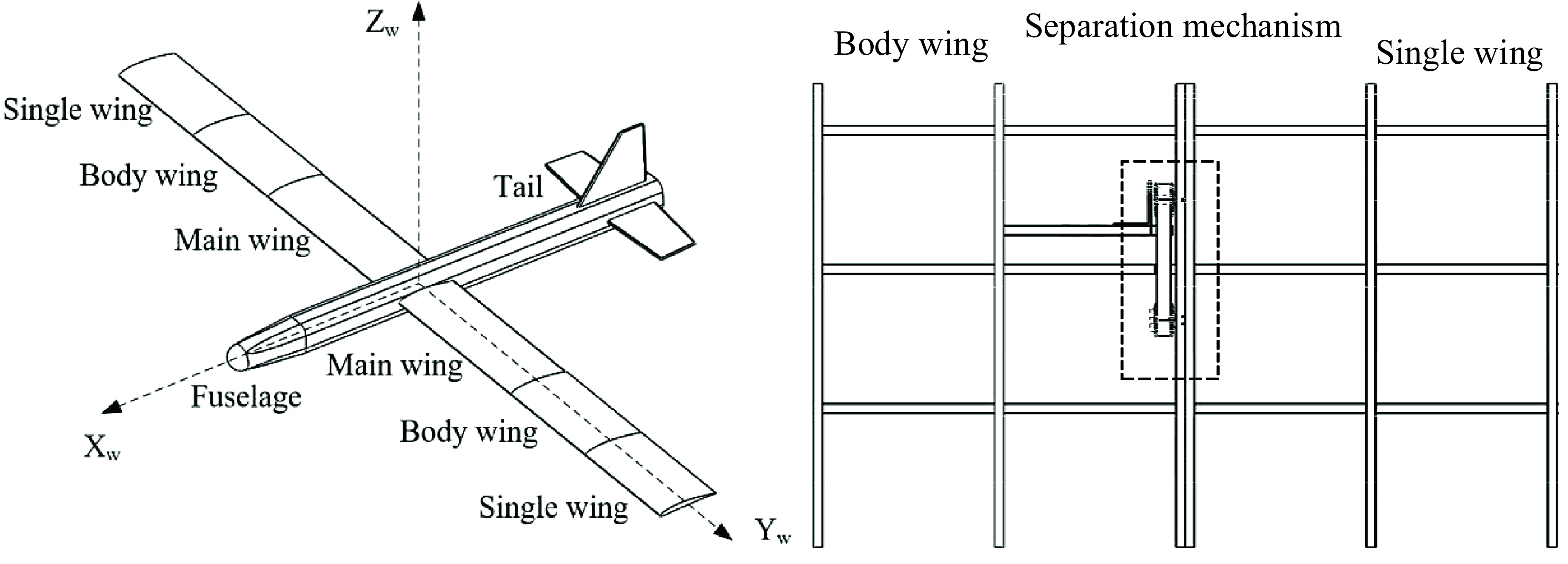
Figure 1. Layout of unlocking and separating mechanism.
In conventional separation mechanisms, both pyrotechnic devices and electromagnetic devices often result in instantaneous impact during the separation process. However, in this study, we have implemented a novel approach by employing a sine function as the design curve for the spiral chute in the separation mechanism. By doing so, we aimed to ensure that the single wing exhibits exceptional low-impact characteristics during separation. The curve-function is shown as follows.
2.2 Separation mechanism working principle
Before separation, the sliding pin is positioned at the bottom of the spiral chute, as depicted in Fig. 2. This restricts the movement of the flange in the shaft direction. Additionally, the three set pins align with the three pin holes in the body wing, which restricts the remaining five degrees of freedom of the individual wing. Consequently, the two wings are interlocked in a rigid connection. During the separation process, the synchronous driving system propels the sliding pins to glide within the spiral chute. This action pushes the flange in an outward direction. Simultaneously, the set pins slide out of the pin holes, enabling the two wings to complete the separation procedure. Due to the sinusoidal function curve design of the spiral chute trajectory, the separation speed and acceleration of the individual wing exhibit a compliant characteristic throughout the separation process. This compliant behaviour eliminates any impact load, thus ensuring the stability of the separation process.
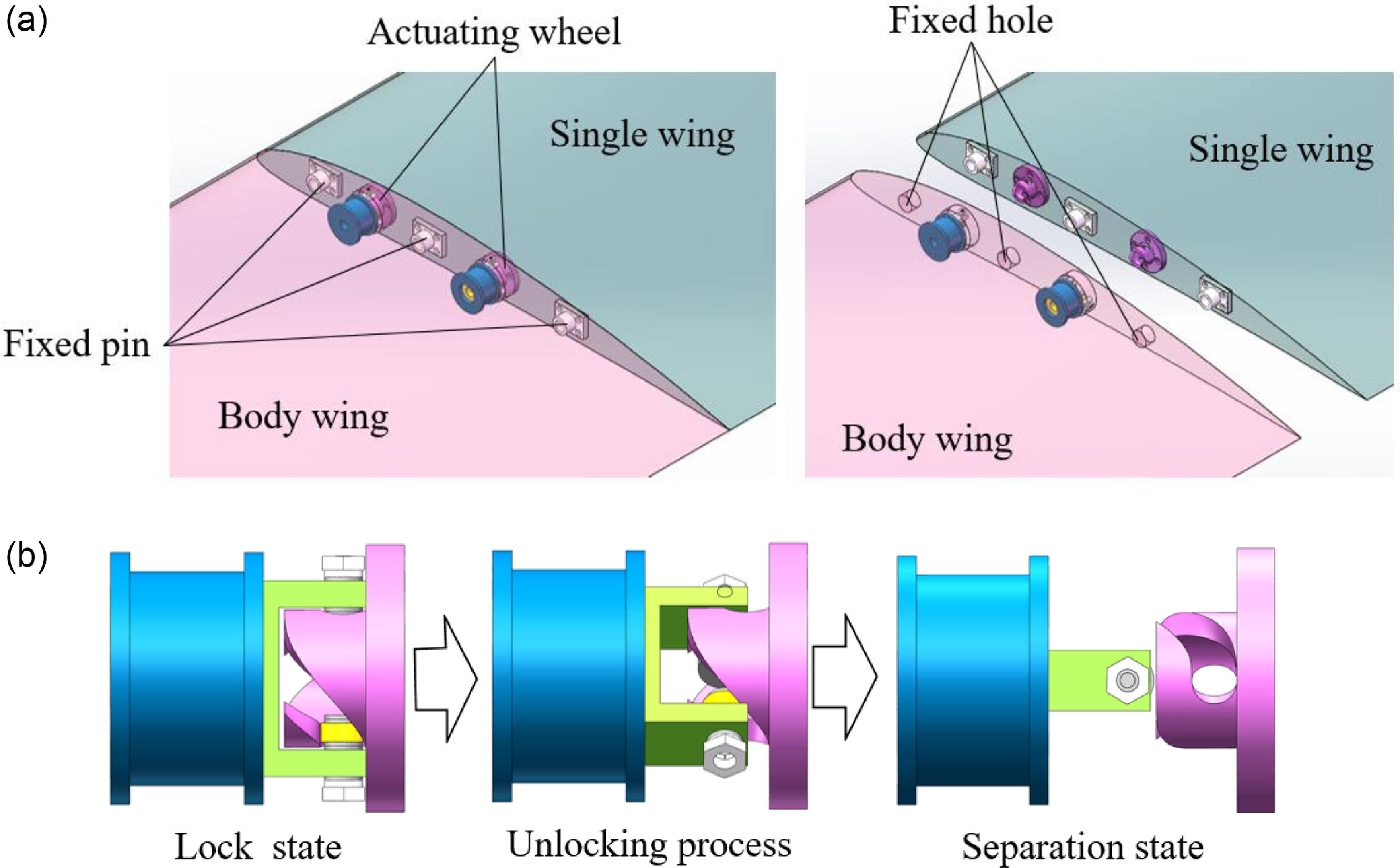
Figure 2. The working principle of the unlocking separation mechanism: (a) the state of the body wing and single wing before and after separation; (b) the process of rotary separation of the separation mechanism.
3.0 Mechanical model
After comprehensively understanding the working principle of the separation mechanism, the next step involves constructing a three-dimensional model of the mechanism. Additionally, the axisymmetric distribution of the spiral chute on the flange is designed by utilising the geometric parameters of the flange and the sine function curve. This approach ensures an accurate and efficient design process. Subsequently, the aerodynamic model of the single wing, the friction model of the separation mechanism, and the unlocking moment model are established. These models allow for the definition of the relationship between the aerodynamic load and the unlocking moment. By analysing this relationship, the necessary conditions for the successful aircraft separation can be derived. This comprehensive approach ensures a thorough understanding of the separation process and enables the realisation of a successful separation event. Because it is essential to guarantee that the mechanical of separation mechanism performance can withstand all flying circumstances, it is necessary to study the dynamic characteristics of the mechanism. To determine the aerodynamic load distribution pattern under full flight conditions, the finite volume method is employed. By considering the maximum aerodynamic load as the externally applied force, the mechanical characteristics of the stress zone within the mechanism are evaluated using finite element analysis. After confirming that the mechanical properties of the separation structure meet the design requirements, the ground separation experimental system is developed. Dynamic loading of aerodynamic loads during single wing separation process achieved through lift traction device and drag traction device, and then separation experiments under typical separation conditions are conducted. In Fig. 3, the analysis process of the whole process is described.
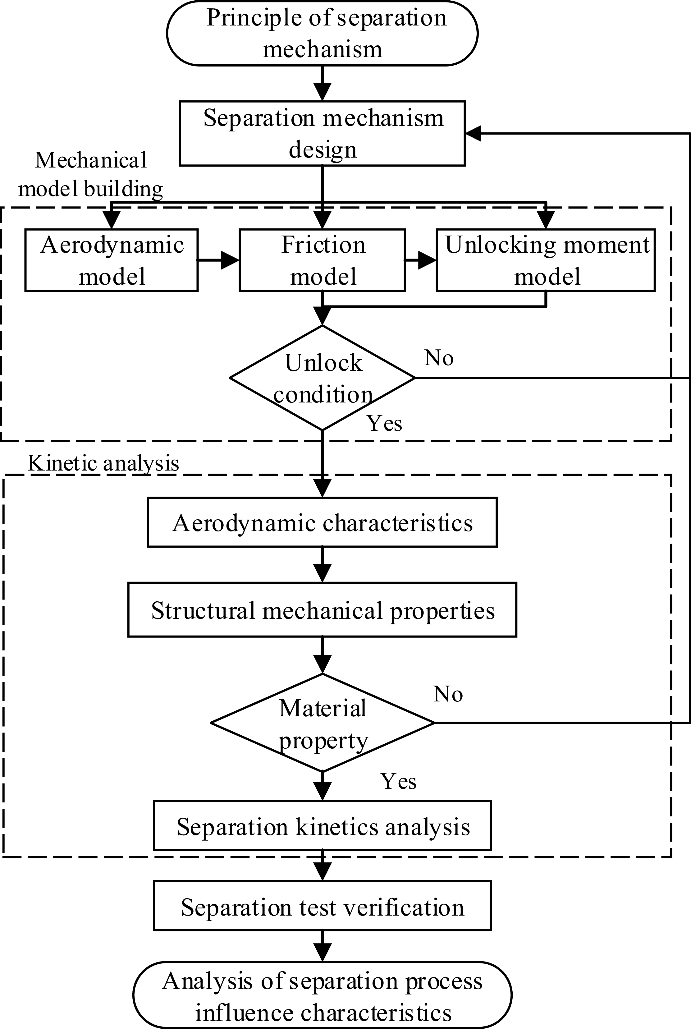
Figure 3. Flow chart of separation mechanism design and analysis.
3.1 Aerodynamic model of single wing
The standard rigid-body dynamic model [Reference Etkin21] is adapted with the addition of forces and moments due to linked aircrafts. The translational and rotational kinematic equations of a fixed-wing aircraft are given by:
 \begin{align}\dot{\boldsymbol{r}} = \boldsymbol{R}_B^I\left[ \begin{array}{l}u\\v\\w\end{array} \right]\end{align}
 \begin{align}\left[\begin{array}{c} {\dot \phi } \\[3pt] {\dot \theta } \\[3pt] {\dot \psi } \end{array} \right] = \left[ \begin{array}{c@{\quad}c@{\quad}c} 1 & {{s_\phi }{t_\theta }} & {{c_\phi }{t_\theta }} \\[3pt] 0 & {{c_\phi }} & { - {s_\phi }}\\[3pt] 0 & {s_\phi }/{c_\theta} & {c_\phi }/{c_\theta }\end{array} \right]\omega \end{align}
 \begin{align} \boldsymbol{R}_B^I = \left[ {\begin{array}{c@{\quad}c@{\quad}c}{{c_\theta }{c_\psi }} & {{s_\phi }{s_\theta }{c_\psi } - {c_\phi }{s_\psi }} & {{c_\phi }{s_\theta }{c_\psi } + {s_\phi }{s_\psi }}\\[3pt]{{c_\theta }{s_\psi }} & {{s_\phi }{s_\theta }{s_\psi } + {c_\phi }{c_\psi }} & {{c_\phi }{s_\theta }{s_\psi } - {s_\phi }{c_\psi }}\\[3pt]{ - {s_\theta }} & {{s_\phi }{c_\theta }} & {{c_\phi }{c_\theta }}\end{array}} \right]\end{align}
The vehicle dynamic equations are given by:
 \begin{align}\left[ \begin{array}{l}{\dot u}\\[2pt]{\dot v}\\[2pt]{\dot w}\end{array} \right] = \frac{1}{m}\left[ {{\boldsymbol{F}_{\rm{A}}} + m\boldsymbol{R}_I^B\left[ \begin{array}{l}0\\[2pt]0\\[2pt]g\end{array} \right] + {\boldsymbol{F}_{\rm{T}}} + {\boldsymbol{F}_{\rm{L}}}} \right] - \omega \times \left[ \begin{array}{l}u\\[2pt]v\\[2pt]w\end{array} \right]\end{align}
The aerodynamic forces and moments are given by:
 \begin{align}{\boldsymbol{F}_{\rm{A}}} = \bar qS\left[ {\begin{array}{c@{\quad}c@{\quad}c}{ - {c_\alpha }}& 0& {{s_\alpha }}\\[3pt]0& {\rm{1}}& 0\\[3pt]{ - {s_\alpha }}& 0& { - {c_\alpha }}\end{array}} \right]\left[ \begin{array}{l}{C_{\rm{D}}}\\[3pt]{C_{\rm{Y}}}\\[3pt]{C_{\rm{L}}}\end{array} \right]\end{align}
 \begin{align}{M_{\rm{A}}} = \bar qS\left[ {\begin{array}{c@{\quad}c@{\quad}c}b & 0 & 0\\[3pt]0 &{\bar c} &0\\[3pt]0 & 0 & b\end{array}} \right]\left[ \begin{array}{l}{C_{\rm{l}}}\\[3pt]{C_{\rm{m}}}\\[3pt]{C_{\rm{n}}}\end{array} \right]\end{align}
The aerodynamic coefficients are obtained using the generic nonlinear aerodynamic model found in [Reference Grauer and Morelli22, Reference Grauer and Morelli23].
3.2 Friction model of set pin
During the separation process, the frictional force generated by the set pin and pin hole will prevent the single wing from moving outward at this time. Let the number of set pins on the single wing be n, Ox is the position of a set pin on the separation surface. Figure 4 depicts the force state of the set pin and the pin hole.
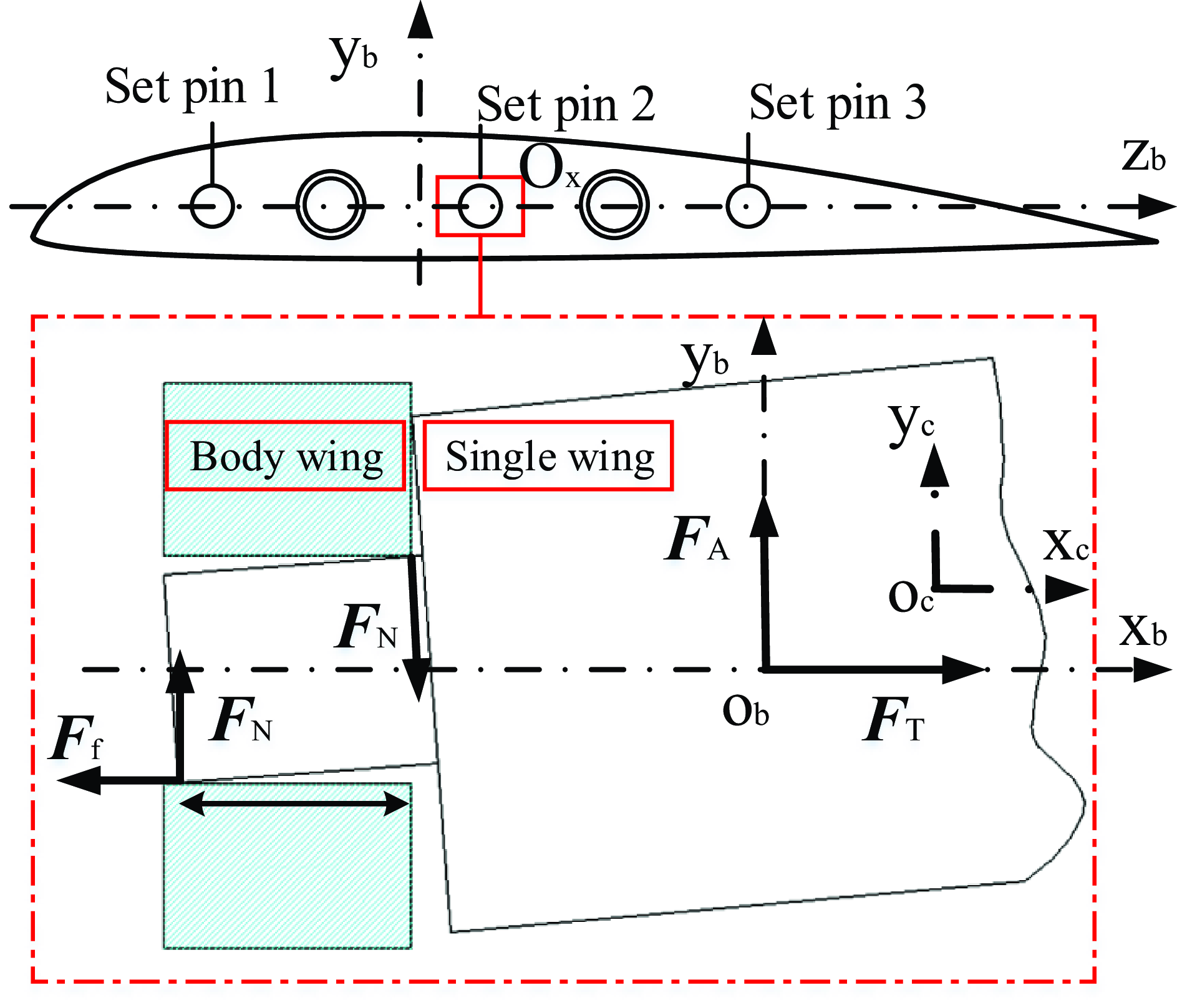
Figure 4. Force analysis of set pin and pin hole.
The total friction force in the single wing’s centroid coordinate system ocxcyczc as follows:
 \begin{align}{\boldsymbol{F}_{\rm{f}}} = \left\{ {\begin{array}{c}{ - \sum\limits_{i = {\rm{1}}}^n {{F_{{\rm{f}}i}}} }\\[6pt]0\\[3pt]0\end{array}} \right\}\end{align}
In the separation process, the torque generated by the set pin is shown as follows:
The torque caused by the set pin friction on the monomer centroid is shown as follows:
 \begin{align}{\boldsymbol{r}_{{\rm{ox}}}} = \left\{ {\begin{array}{*{20}{c}}{{x_{{\rm{ocx}}}}}\\{{y_{{\rm{ocx}}}}}\\{{z_{{\rm{ocx}}}}}\end{array}} \right\} = \left\{ {\begin{array}{*{20}{c}}{{x_{{\rm{ox}}}} - {x_{{\rm{co}}}}}\\{{y_{{\rm{ox}}}} - {y_{{\rm{co}}}}}\\{{z_{{\rm{ox}}}} - {z_{{\rm{co}}}}}\end{array}} \right\}\end{align}
The balance equation between the external torque generated by the single wing aerodynamic force and the internal torque of the set pin is shown as follows:
 \begin{align}{\boldsymbol{M}_{\rm{A}}} = \left\{ \begin{array}{l}{M_{{\rm{xc}}}}\\[4pt]{M_{{\rm{yc}}}}\\[4pt]{M_{{\rm{zc}}}}\end{array} \right\}\end{align}
Since the set pin has no torque in the yz plane, friction produces an internal torque as shown as follows:
 \begin{align}{\boldsymbol{M}_{{\rm{f2}}}} = \left\{ {\begin{array}{c}0\\[3pt]{{M_{{\rm{f2y}}}}}\\[3pt]{{M_{{\rm{f2z}}}}}\end{array}} \right\} = \left\{ {\begin{array}{c}0\\[5pt]{ - {M_{{\rm{yc}}}} + \sum\limits_{i = {\rm{1}}}^n {{z_{{\rm{ox}}i}}{F_{{\rm{f}}i}}} }\\[7pt]{ - {M_{{\rm{zc}}}} - \sum\limits_{i = {\rm{1}}}^n {\left( {{y_{{\rm{ox}}i}} - {y_{{\rm{co}}}}} \right){F_{{\rm{f}}i}}} }\end{array}} \right\}\end{align}
According to Coulomb’s law of friction, the friction force on any set pin is shown as follows:
The results obtained by substituting in Equation (15) are as follows:
 \begin{align}{\boldsymbol{M}_{{\rm{f2}}}} = \left\{ {\begin{array}{*{20}{c}}0\\[4pt]{ - {M_{{\rm{yc}}}} + \sum\limits_{i = {\rm{1}}}^n {{z_{{\rm{ox}}i}}{f_{\rm{d}}} \cdot \left( {{\rm{2}}{F_{\rm{N}}}} \right)} }\\[6pt]{ - {M_{{\rm{zc}}}} - \sum\limits_{i = {\rm{1}}}^n {\left( {{y_{{\rm{ox}}i}} - {y_{{\rm{co}}}}} \right){f_{\rm{d}}} \cdot \left( {{\rm{2}}{F_{\rm{N}}}} \right)} }\end{array}} \right\}\end{align}
Assuming that each set of set pins provides the same internal torque, the internal torque of n set pins is shown as follows:
Equations (17) and (18) are identical in value, and the necessary conditions for the existence of positive pressure of set pin can be obtained as follows:
 \begin{align} n \cdot {\delta _{\rm{L}}} \gt 2 {f_{\rm{d}}}\sqrt {{{\left( {\sum\limits_i {{z_{{\rm{ox}}i}}} } \right)}^{\rm{2}}} + {{\left( {\sum\limits_i {{y_{{\rm{ox}}i}}} } \right)}^{\rm{2}}}} \end{align}
At the same time, the necessary conditions for the separation of a single wing are as follows:
3.3 The relationship between unlocking torque and friction
Figure 5 depicts the mechanical model of the separating mechanism. Figure 5a displays the stress state of the rotating pin at any given time, and Fig. 5b depicts the stress state of the unlocking and flange at the same time.

Figure 5. Force analysis model of unlocking and separating mechanism: (a) force analysis of sliding pin; and (b) force analysis of unlocking flange.
The force equation of the sliding pin is as follows:
 \begin{align}\left\{ \begin{array}{l}{\boldsymbol{F}_{{\rm{xx}}}} = {\boldsymbol{F}_{{\rm{xx}}}}^{{\rm{fix}}} - {\boldsymbol{F}_{{\rm{xN}}}}{\rm{sin}}\theta - {\boldsymbol{F}_{{\rm{x}}f}}{\rm{cos}}\theta \\[4pt]{\boldsymbol{F}_{{\rm{xy}}}} = {\boldsymbol{F}_{{\rm{xy}}}}^{{\rm{fix}}} + {\boldsymbol{F}_{{\rm{xN}}}}{\rm{cos}}\theta - {\boldsymbol{F}_{{\rm{x}}f}}{\rm{sin}}\theta \\[4pt]{\boldsymbol{M}_{{\rm{xo}}}} = \boldsymbol{M}_{{\rm{xo}}}^{{\rm{fix}}} - {\boldsymbol{F}_{{\rm{x}}f}} \cdot r\end{array} \right.\end{align}
Based on the actual motion of the sliding pin, the unlocking conditions are as follows:
 \begin{align}\left\{ \begin{array}{l} {\boldsymbol{F}_{{\rm{xx}}}} = {\dfrac{{\boldsymbol{M}_0}}{{\rm{2}}{l_0}}}{\rm{ \gt 0}} \\[6pt] {\boldsymbol{F}_{{\rm{xy}}}} = 0 \\[4pt] {\boldsymbol{M}_{{\rm{xo}}}} = 0 \end{array} \right.\end{align}
The unlocking torque is provided by the sliding pin support in Fig. 2.
The force equation of the flange under the rotation of the sliding pin is as follows:
 \begin{align}\left\{ \begin{array}{l}{\boldsymbol{F}_{{\rm{px}}}} = {\boldsymbol{F}_{{\rm{px}}}}^{{\rm{fix}}} + {\boldsymbol{F}_{{\rm{pN}}}}{\rm{sin}}\theta + {\boldsymbol{F}_{{\rm{p}}f}}{\rm{cos}}\theta \\[4pt]{\boldsymbol{F}_{{\rm{py}}}} = {\boldsymbol{F}_{{\rm{py}}}}^{{\rm{fix}}} - {\boldsymbol{F}_{{\rm{pN}}}}{\rm{cos}}\theta + {\boldsymbol{F}_{{\rm{p}}f}}{\rm{sin}}\theta \\[4pt]{\boldsymbol{M}_{{\rm{po}}}} = {\boldsymbol{M}_{{\rm{po}}}}^{{\rm{fix}}} - {\boldsymbol{F}_{{\rm{pN}}}} \cdot {l_{\rm{1}}} - {\boldsymbol{F}_{{\rm{p}}f}} \cdot {l_{\rm{2}}}\end{array} \right.\end{align}
Based on the actual motion of the sliding pin, the unlocking conditions of the flange are as follows:
 \begin{align}\left\{ \begin{array}{l} {\boldsymbol{F}_{{\rm{px}}}} = 0 \\[4pt] {\boldsymbol{F}_{{\rm{py}}}} \lt 0 \\[4pt] {\boldsymbol{M}_{{\rm{po}}}} = 0 \end{array} \right.\end{align}
According to the established unlocking and separation conditions, it can be seen that the unlocking torque is related to aerodynamic force, friction coefficient, including angle of spiral chute and other factors. The relationship between the unlocking torque and aerodynamic angle-of-attack can be obtained through calculation, as shown in Fig. 6. According to the calculation results, when the angle-of-attack reaches the maximum 30°, the maximum unlocking torque
![]() ${M_{\rm{T}}}^{{\rm{max}}} = 2 {\rm{.064\, N/m}}$
is required.
${M_{\rm{T}}}^{{\rm{max}}} = 2 {\rm{.064\, N/m}}$
is required.
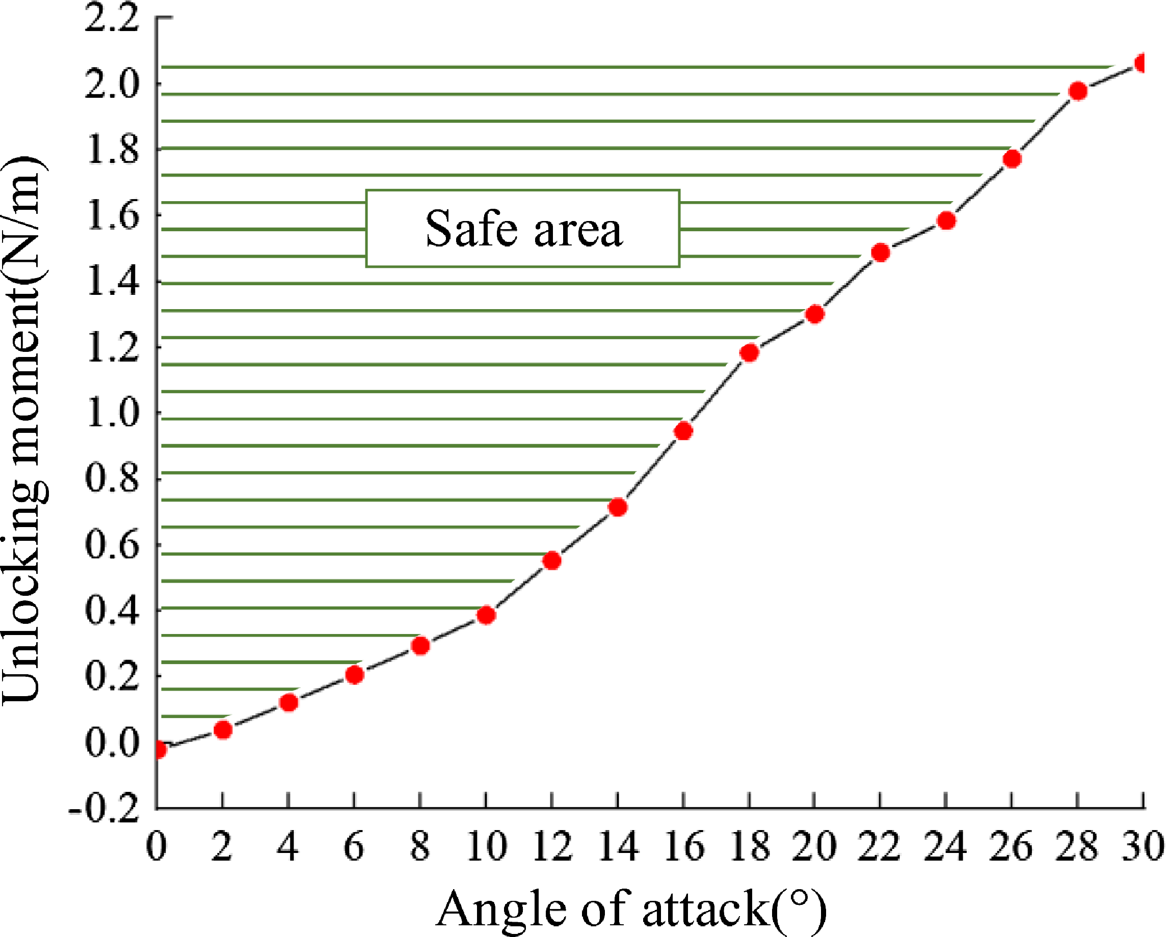
Figure 6. Relation between unlocking torque and aerodynamic angle-of-attack.
3.4 Dynamic characteristic
Under the actual operating conditions, a comprehensive analysis is conducted to assess the aerodynamic properties of the individual body, the mechanical behaviour of the set pin, and the dynamics of the unlocking mechanism. By considering the various forces acting on the separation mechanism, the overall performance and functionality of the mechanism can be thoroughly evaluated. This thorough analysis ensures the mechanism’s effectiveness and reliability during operation.
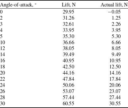
A Menter’s shear stress transfer (SST) turbulence model with a cruise speed of Vf = 60 m/s, a cruise altitude of H = 1,000 m, a flight angle-of-attack that ranges from 0 to 30°, and a single maximum design mass of M = 3 kg is used by the atmospheric model during the simulation stage of aerodynamic characteristics. Based on the monoplane’s flight conditions, the aerodynamic loads are computed. The outcomes of the single-wing aerodynamic simulation analysis in this study are shown in Fig. 7. Table 1 displays the computation’s outcomes.

Figure 7. Aerodynamic simulation results of combined UAV.
Table 1. Aerodynamic load calculation results of single wing
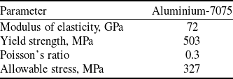
The manoeuvering load and gust wind load during flight exacerbate the force condition of the stationary pin. The force condition of the stationary pin is further aggravated by the manoeuvering load and gust wind load experienced during flight. Therefore, it is crucial to perform a mechanical verification of the set pin to ensure that the maximum contact stress remains below the permissible stress of the material. This verification is necessary to ensure that the separation mechanism meets the design requirements under all operating situations. The set pin is constructed using the 7075 aluminum alloy, and Table 2 provides an overview of the material characteristics.
Table 2. Material parameters
A finite element model is developed to analyse the bearing structure and separation mechanism of the combined UAV. The model considers the application of the maximum pneumatic force on the single wing, allowing for the calculation of the stress distribution within the bearing structure under this force. The results of the calculations indicate that the highest stress concentration occurs at the middle two set pins, reaching a maximum value of 131 MPa. This finding is illustrated in Fig. 8, and it confirms that the stress levels are within the acceptable range for the mechanical properties of the material, satisfying the requirements.
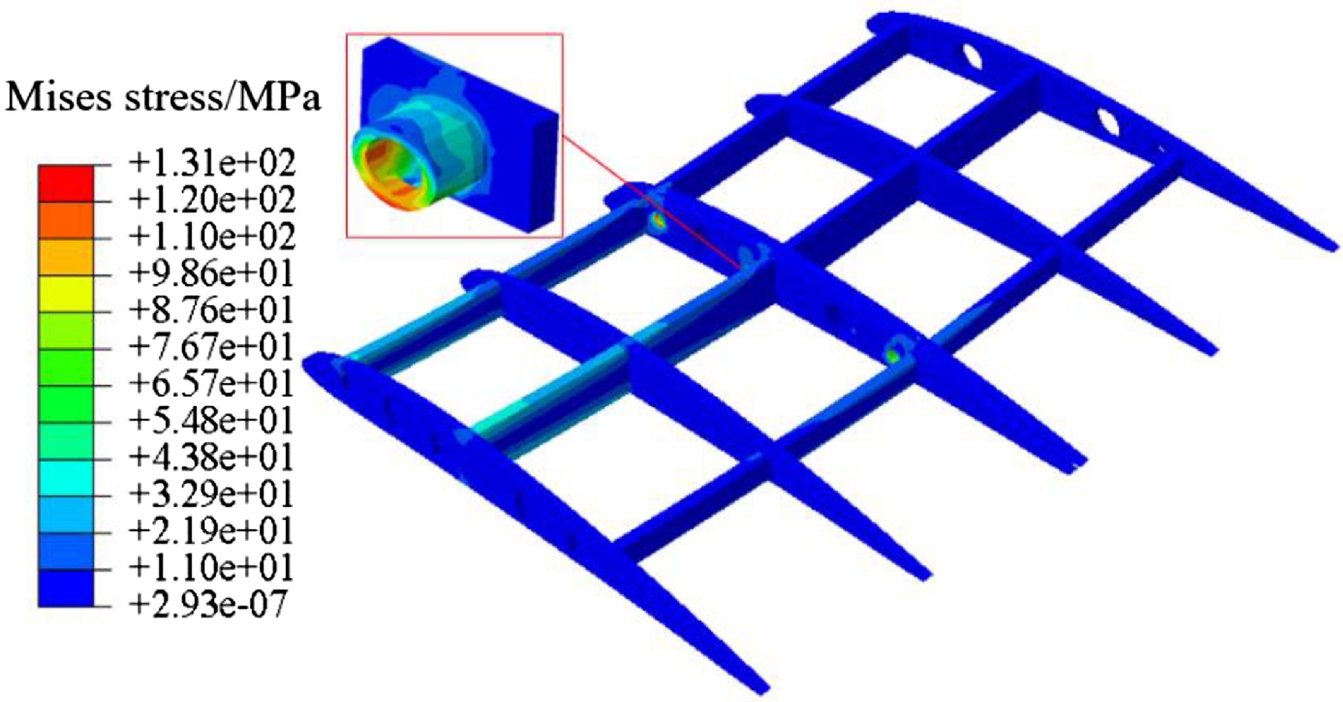
Figure 8. Stress distribution under maximum force.
In order to determine the kinematic properties of the separation mechanism, an analysis was conducted on the separation dynamics of the mechanism throughout the entire mission cycle. The model used for analysis is illustrated in Fig. 9. The separation action time (T) is set to 1 second, and the longitudinal displacement, velocity, and acceleration data of the single wing during the separation process are obtained with the centre of mass O of the single wing serving as the reference point for attitude data, as depicted in Fig. 10. The calculation results reveal that both the single wing separation displacement curve and separation velocity curve exhibit sinusoidal characteristics. The separation acceleration data display sawtooth curves within a narrow range due to the influence of contact parameter settings such as material contact stiffness (k), force index (e), damping (c), and magnetic permeability (s). However, after being fitted with a nonlinear curve function, they still exhibit distinct characteristics of a sinusoidal function distribution. Equation (26) depicts the data-fitted sinusoidal curve equation.
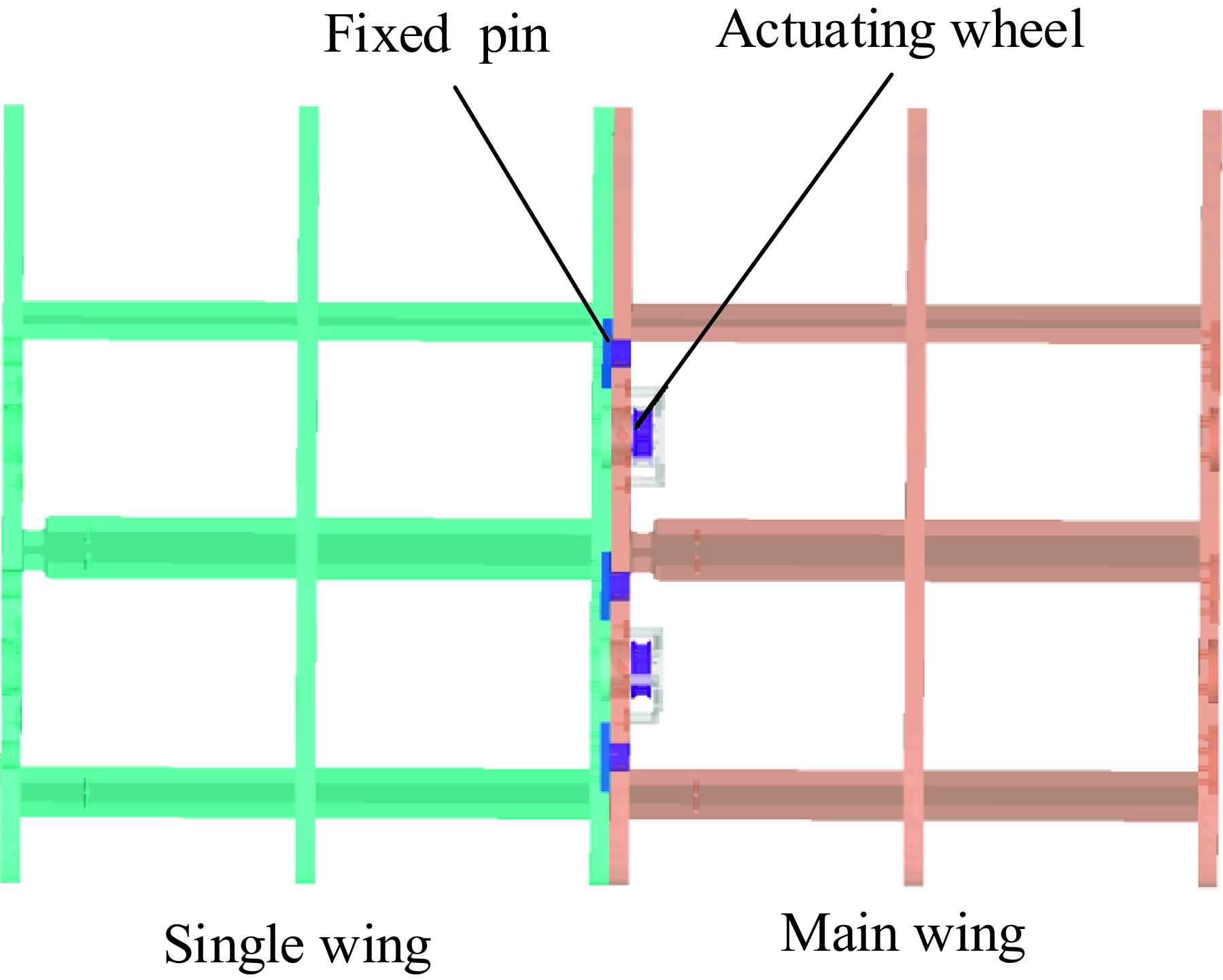
Figure 9. Separation kinetics analysis model.
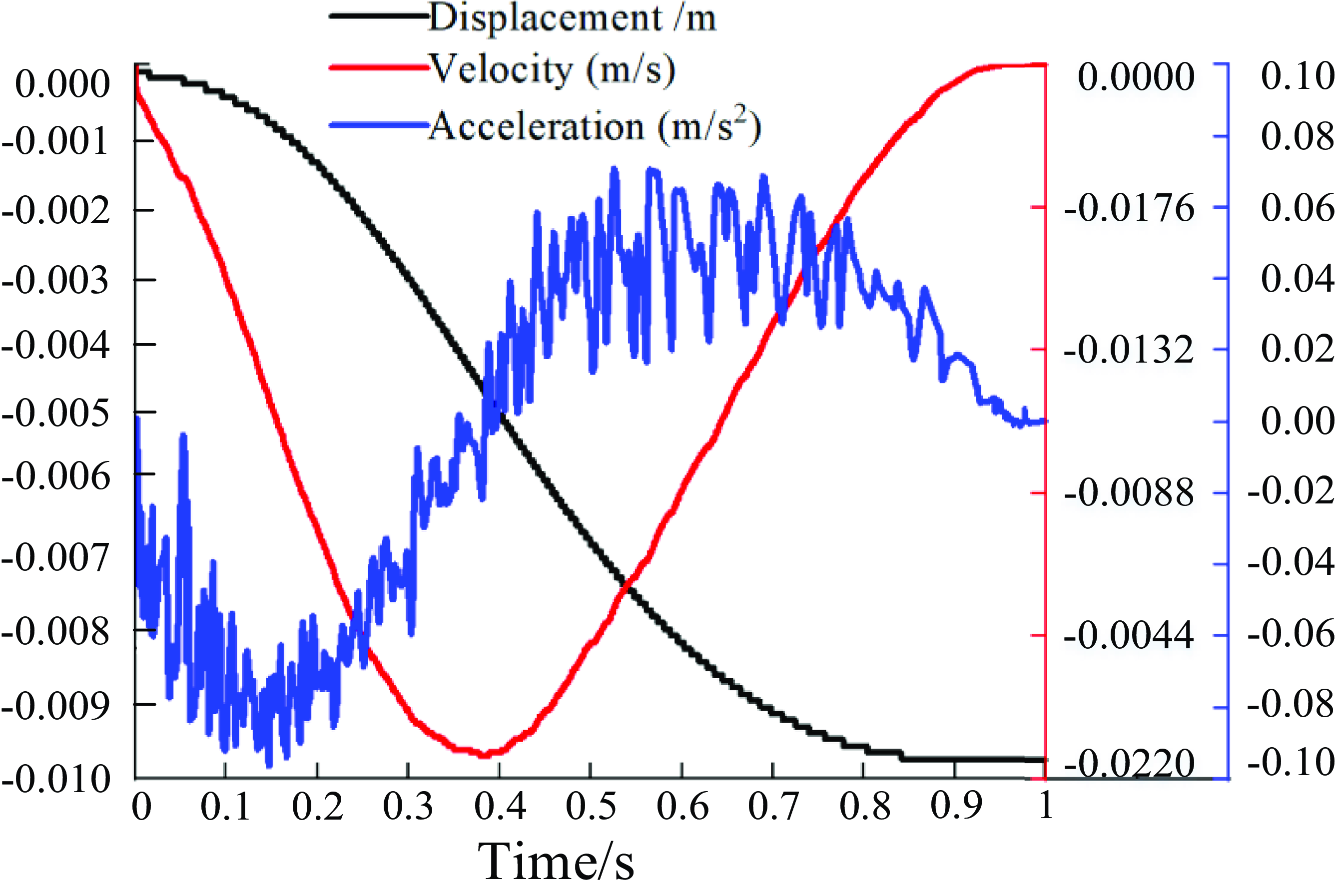
Figure 10. Separation kinetic parameter curve.
It can be observed that the monoplane motion parameters, such as separation displacement, separation speed, and separation acceleration, do not experience sudden changes during the separation process. This indicates that the separation mechanism can fulfill the demand for fast, low-impact, and smooth separation tasks.
In the separation process, the force exerted by the single wing on the body wing primarily influences the aircraft’s rolling stability, while having minimal impact on its pitching and yawing moments. Therefore, this study focuses mainly on analysing the static rolling stability, as depicted in Fig. 11. The monomer applies a rolling moment of 0.75 N/m to the main body during separation, which is significantly lower than the maximum rolling moment. Hence, this paper demonstrates favourable characteristics of low impact for the proposed separation mechanism.
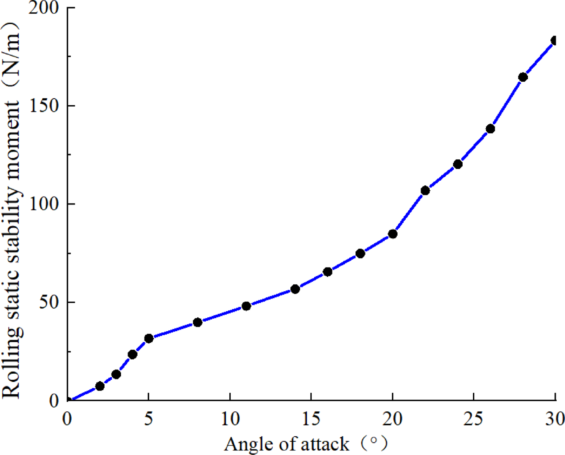
Figure 11. Rolling static stability curve.
4.0 Experimental verification
4.1 Separation experiment
Based on the research conducted on the mathematical model and finite element model, a combined UAV experimental system was designed and constructed. This system was developed to simulate the hanging principle and provide an equivalent external force during the separation process of the single wing, as illustrated in Fig. 12. Subsequently, experimental research was conducted to investigate the separation of the single wing under aerodynamic load.
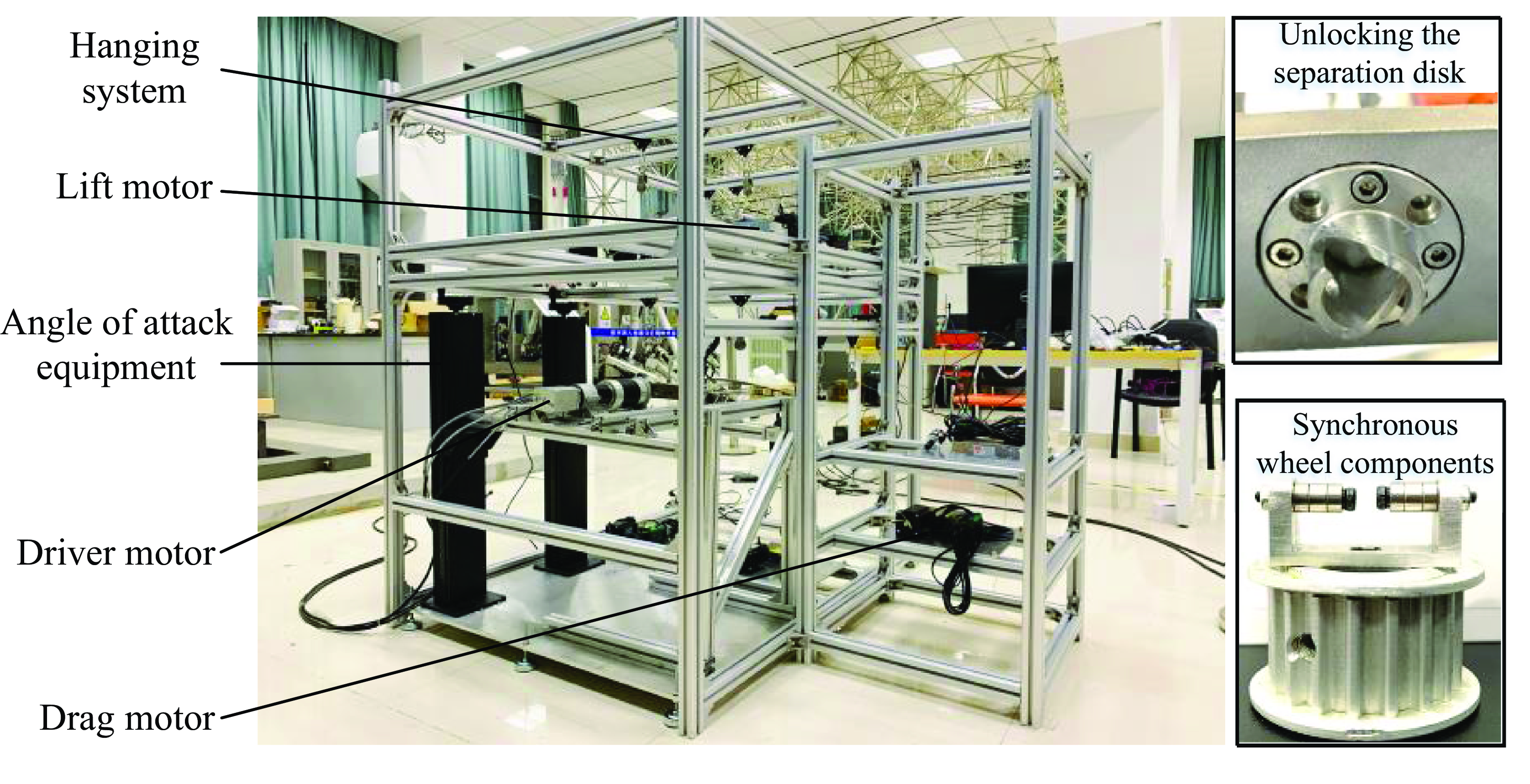
Figure 12. Pneumatic load simulation test platform.
Before the experiment started, the angle-of-attack of the experimental setup was adjusted to 3° in order to simulate the separation characteristics in the case of the optimal lift-to-drag ratio, and the sensor was adjusted to the position of the single wing centre of mass. According to the simulation calculation results (Table 1), the lift motor and drag motor were adjusted to make the load lift drag consistent with the aerodynamic simulation calculation results at the 3° angle-of-attack. Start the drive motor and collect the acceleration data during the separation of the monocoque, as shown in Figs. 13 and 14. Considering factors such as processing errors and response delays in the experiment, multiple separation experiments were conducted under 3° conditions, and the experimental results are shown in Fig. 15.
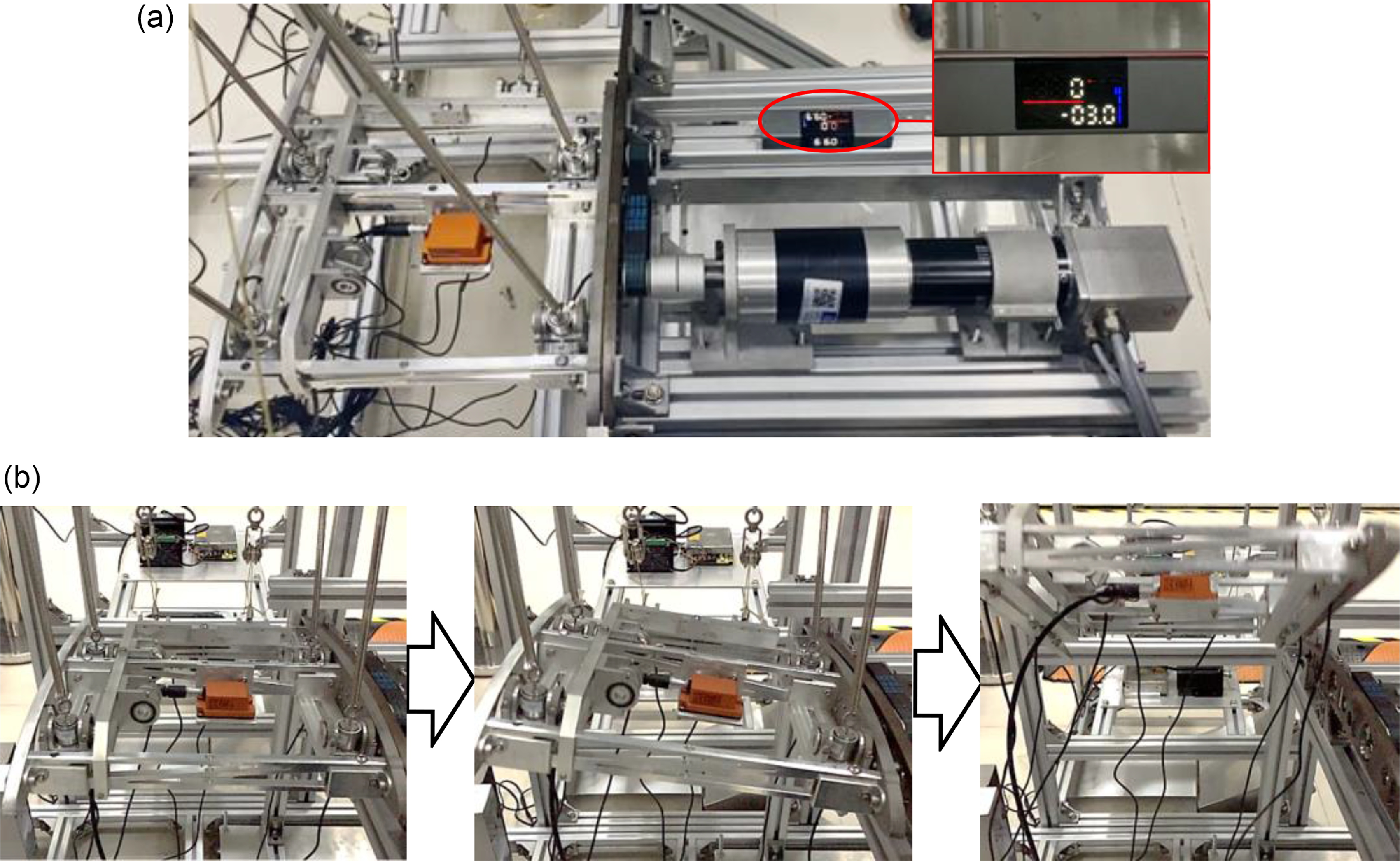
Figure 13. Separation experiment process: (a) single wing pre-separation state;and (b) single wing separation process.
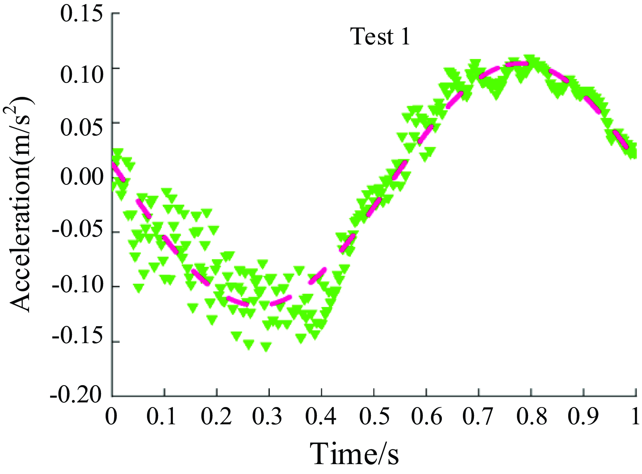
Figure 14. Single wing separation acceleration curve.
The above five groups of data are analysed by superposition, and the mean data after superposition is fitted by nonlinear function. The fitting equation is presented in Equation (27). The experimental results show that the centroid acceleration in single wing separation satisfies the sinusoidal function characteristics.
4.2 Analysis of influencing factors
In order to further study the safety of single wing separation process, this paper analyses the influence of different flight speeds and flight angle-of-attack on the separation process. The values of flight speed parameters are shown in Table 3, and the values of flight angle-of-attack are shown in Table 4.
Table 3. Flight speed parameters table

Table 4. Flight angle-of-attack parameter table

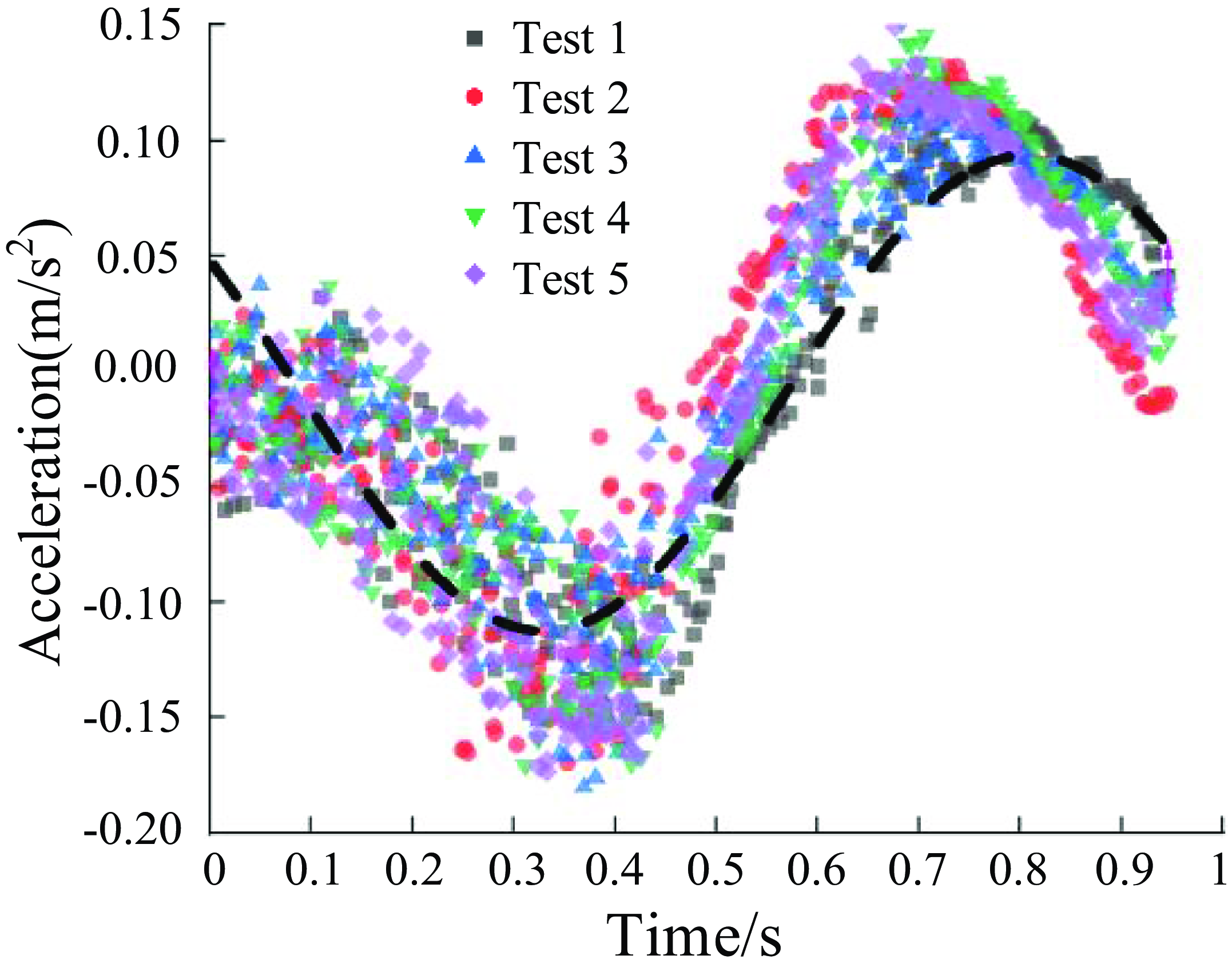
Figure 15. Acceleration stacking mean fitting function.
The law of motion variation can be ascertained by analysing the trend of velocity variation in the centroid of the single wing. Figure 16 presents the velocity curve of the single wing in the separation direction. The results indicate that as the angle-of-attack remains constant, the flight velocity gradually increases, subsequently augmenting the velocity of separation for the individual wing. Moreover, the findings reveal that alterations in flight velocity have no detectable effect on the separation process of the single wing. When the flight velocity remains steady and the flight angle-of-attack falls within the range of 3° to 5°, the separation velocity displays cosine-like characteristics. However, a significant alteration in the single wing’s velocity occurs at the 0.97-second mark when the angle-of-attack reaches 6°. Additionally, at an angle-of-attack of 7°, the velocity of the single wing also undergoes a sudden and pronounced change at 0.91 seconds. These findings indicate that the separation process is significantly influenced by the flight angle-of-attack, suggesting that the safe separation angle-of-attack should be maintained below 6°. Furthermore, the results demonstrate that the flight speed has minimal impact on the separation process.
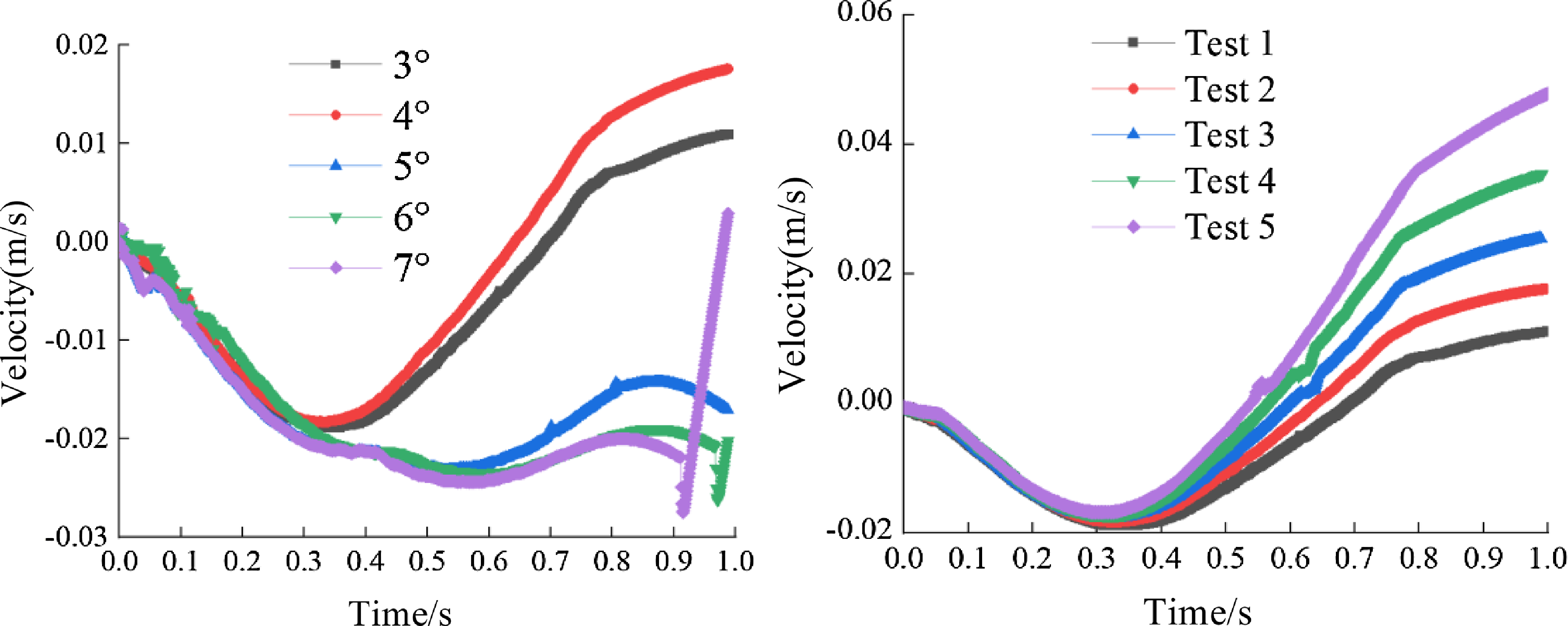
Figure 16. Analysis results of influencing factors.
5.0 Conclusion
-
(1) A wingtip separation mechanism with low-impact characteristics was designed for the combined aircraft, and the dynamics is calculated for all flight conditions. Based on the N-S equation and the Coulomb friction law, the maximum unlocking torque required for the mechanism was obtained as 2.064 N/m.
-
(2) The kinetic model of the separation mechanism was developed and validated through experimental prototyping. By simulating the separation process, we determined that the acceleration of the separation mechanism followed a sinusoidal function, in accordance with the expected behaviour. To increase the reliability of the experimental data, we conducted a series of five experiments under identical working conditions. The resulting data sets were processed using fitting functions, revealing that the measured acceleration also adhered to the sinusoidal function, further validating our findings. Furthermore, the maximum acceleration recorded during the separation process was determined to be 1.01 m/s2. The consistency between the two calculation results serves to confirm that the separation mechanism demonstrates low-impact characteristics throughout the separation process. This outcome aligns with the criteria for compliant design, thereby fulfilling the necessary requirements.
-
(3) This paper focuses on the comparative analysis of two crucial factors, namely flight speed and flight angle-of-attack, which significantly impact the separation process. By analysing and examining these parameters, we aim to gain a deeper understanding of their respective influences in the context of the studied mechanism. The analysis indicate that the flight speed has a relatively minimal impact on the separation process, whereas the flight angle-of-attack plays a more influential role. Specifically, when the flight angle-of-attack is below 5°, the single wing can be successfully separated. However, if the flight angle-of-attack exceeds 6°, the single wing is prone to collide with the body wing during separation. Consequently, it is recommended to maintain the angle-of-attack of the single wing below 6° in order to ensure a smooth separation process.
Acknowledgments
This study is supported by the following projects: 1. National Natural Science Foundation of China (Project Number: 52075242); 2. National Science and Technology Special (Project Number: 2021-312 JCIO-JJ-0233); 3. National Science and Technology Special (Project Number: 23-TQ01-04-ZT-01-017); 4. Supported by the National Science and Technology Special Project (Project number: D050202); 5. Supported by the Central University Basic Research Fund (Project Number: NT2022026). All authors would like to thank them.
Data availability statement
Some or all data, models, or code that support the findings of this study are available from the corresponding author upon reasonable request.


